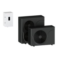
The Vitocal 100-AW AM2V is an air-to-water heat pump system designed for heating and cooling buildings, as well as heating domestic hot water. The system comprises two main modules: an outdoor unit and an indoor unit.
Function Description
The outdoor unit is responsible for capturing heat from the environment and transferring it to the building's heating circuit. It uses an evaporator to transfer low-temperature air heat to a refrigerant, which then evaporates into a gas. This gas is compressed, raising its temperature, and directed to a condenser. In the condenser, heat is transferred to the central heating system, and the cooled liquid refrigerant returns to the evaporator via an expansion valve, restarting the cycle. For cooling, this process is reversed, extracting heat from the building and discharging it outdoors. All refrigeration circuit components, including the refrigeration circuit controller with an electronic expansion valve, are located in the outdoor module. The compressor power is adjusted by an inverter based on operating conditions.
The indoor unit's principle of operation involves demand-dependent capacity control of the heat pump compressor, with activation of an electrical auxiliary heater via its controller. The indoor module controller regulates heating output according to a pre-set heating curve. If the heat pump cannot meet the building's heating demand alone, the controller automatically activates the electrical auxiliary heater to achieve the desired heating medium temperature.
The indoor and outdoor modules are connected via hydronic lines. A high-efficiency circulation pump (secondary pump) in the indoor module supplies heating medium to the secondary circuit. A central 3-way diverter valve manages switching between space heating and domestic hot water heating. The entire system is monitored and controlled by the heat pump controller, which is integrated into the indoor module and communicates with the outdoor module via a bus.
Air-to-water heat pumps operate efficiently within specific outdoor temperature ranges, typically between -13°F and 113°F (-25°C and +43°C). Outside these limits, the heat pump may switch off periodically, and the controller will activate auxiliary heating equipment to meet demand.
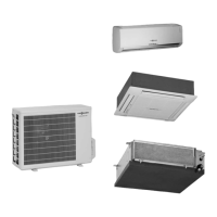
The system supports up to two heating/cooling circuits: one without a mixer and one with a mixer. It can also cool via up to two heating/cooling circuits.
Important Technical Specifications
Indoor Unit:
- Models: AM2V 020028, AM2V 034043, AM2V 051078
- Electrical Data:
- Power Supply: 230 VAC, 1 Phase, 60 Hz
- Amperage (FLA): 31 A (020028, 034043), 43 A (051078)
- Maximum Fuse (Amps): 40 A (020028, 034043), 50 A (051078)
- Electric Heater Output: 6 kW (20500 BTU) for 020028/034043 (2 elements), 9 kW (30700 BTU) for 051078 (3 elements)
- Hydronic Data:
- Hydronic connection: 1-1/4 in. NPT (Male Threads)
- Min. Operating Pressure: 8 PSI (0.5 bar)
- Max. Operating Pressure: 30 PSI (2 bar)
- Max. System Temperature: 140°F (60°C)
- Max. DHW Temperature: 167°F (75°C)
- Max. Operating Temperature: 165°F (74°C)
- Fixed High Limit: 186°F (86°C)
- Expansion vessel volume: 3.2 USG (12 l)
- Expansion vessel precharge: 14 PSI (1 bar)
- Minimum flow: 2.6 GPM (0.6 m³/h) for 020028, 3.1 GPM (0.7 m³/h) for 034043, 3.7 GPM (0.85 m³/h) for 051078
- Maximum flow: 4.4 GPM (1.0 m³/h) for 020028, 7.5 GPM (1.7 m³/h) for 034043, 12.8 GPM (2.9 m³/h) for 051078
- Pressure drop: 0.6 ft. of hd (2 kPa) for 020028, 1.6 ft. of hd (5 kPa) for 034043, 5.0 ft. of hd (15 kPa) for 051078
- Minimum Relief Valve Capacity: 510 MBH
- Dimensional Data (H x W x D): 28-1/2 x 16-1/4 x 12-3/4 in. (723 x 416 x 323 mm)
- Weight: 64 lbs (29 kg)
Outdoor Unit:
- Heating Capacity: 20.5 MBH (6.0 kW) for 020028, 34.0 MBH (10.0 kW) for 034043, 58.0 MBH (17.0 kW) for 051078
- Cooling Capacity: 1.4-1.5 Tons (5.0-5.2 kW) for 020028, 2.8-3.0 Tons (9.8-10.5 kW) for 034043, 4.2-4.3 Tons (14.7-15.1 kW) for 051078
- Refrigerant: R32, with factory charges of 2.43 lbs (1.1 kg) for 020028, 3.97 lbs (1.8 kg) for 034043, and 4.41 lbs (2.0 kg) for 051078. Global Warming Potential (GWP) of R32 is 675/677.
- Max. Allowable Pressure (Heating/Cooling): 725/624 PSIG (5.0/4.3 MPa) for 020028, 740/609 PSIG (5.1/4.2 MPa) for 034043, 972/624 PSIG (6.7/4.3 MPa) for 051078
- Min./Max. Operating Pressure (Low/High Side): 305/638 PSIG (2.1/4.4 MPa) for all models
- Electrical Data:
- Power Supply: 208/230 VAC, 1 Phase, 60 Hz
- Total Electrical Load: 13.0 A (020028), 21.8 A (034043), 35.1 A (051078)
- Minimum Circuit Ampacity: 17 A (020028), 28 A (034043), 44 A (051078)
- Maximum Fuse: 25 A (020028), 45 A (034043), 70 A (051078)
- Air and Noise:
- Max. sound pressure level at 3.3 ft. (1m): 52 dB(A) for 020028, 55 dB(A) for 034043, 56 dB(A) for 051078
- Max. sound power level: 60 dB(A) for 020028, 63 dB(A) for 034043, 64 dB(A) for 051078
- Dimensional Data (H x W x D):
- 020028: 31-1/4 x 46 x 15-3/4 in. (795 x 1165 x 400 mm), Weight: 198 lbs (90 kg)
- 034043: 36-1/2 x 50-3/4 x 18-1/8 in. (928 x 1285 x 460 mm), Weight: 291 lbs (132 kg)
- 051078: 52-3/8 x 49-1/4 x 19-1/2 in. (1329 x 1250 x 495 mm), Weight: 353 lbs (160 kg)
Usage Features
The Vitocal 100-AW AM2V features a user-friendly interface with a navigation dial and mode selector dial.
- Operating Modes: Winter (Space heating + DHW), Summer (Space Cooling + DHW), and Standby (Frost Protection Active).
- Display: The home screen shows basic heat pump parameters. Error or warning indications are displayed if issues occur.
- Menus:
- Diagnostics Menu: Displays current operating conditions of indoor and outdoor units.
- Settings Menu: Allows adjustment of user preferences like room temperature setpoint, DHW temperature setpoint, and time schedules.
- Service Menu: Provides access for installers and service contractors to configure the heating system, view input/output signals, and current parameters (requires an access code).
- Time Schedules: Up to 8 space heating time schedules with five editable time frames and different temperature setpoints. Two DHW temperature setpoints are available. DHW recirculation and space cooling also have programmable start and end times.
- DHW Tank Hygiene Function: Available for systems with indirect DHW storage tanks, allowing water to be heated above 140°F (60°C) once a week or daily for an hour to prevent bacterial growth.
- Heating Curve Adjustment: The controller maintains central heating system temperature based on outdoor temperature. Users can adjust the slope and shift of the heating curve to match building characteristics, climate zone, and heating system type.
- Time Schedule Override: Allows temporary override of active heating/cooling functions (Temporary Hold, Holiday Override, Manual Temp. Hold).
- Initial Start-up: Guides users through selecting operating language and connected outdoor unit model.
Maintenance Features
- Product Documentation: All applicable documentation should be read and stored near the heat pump for future reference by service personnel.
- Professional Installation and Service: Installation, adjustment, service, and maintenance must be performed by a licensed professional heating contractor. There are no user-serviceable parts.
- Safety Precautions:
- Always switch off power supply to indoor and outdoor units before working on the system.
- Wait at least 4 minutes after power shutdown before removing covers to allow voltage to drop.
- Wear suitable personal protective equipment.
- Avoid contact with hot or cold surfaces.
- Discharge static electricity before working on electronic assemblies.
- Do not drill or apply heat to a refrigerant circuit.
- Prevent direct contact with liquid and gaseous refrigerant and never breathe in refrigerant vapors.
- Support piping properly; do not use the indoor unit for support.
- Ensure proper ventilation, especially in the outdoor unit's floor area, to prevent accumulation of flammable refrigerant.
- Use only genuine Viessmann spare parts for replacements.
- Refrigerant Handling:
- The outdoor unit contains flammable R32 refrigerant. Ensure good ventilation, keep ignition sources away, and use explosion-protected tools when working on the refrigerant circuit.
- Refrigerant drained must be properly disposed of by authorized contractors.
- Check the refrigerant circuit for leaks before and during work.
- An explosion prevention plan must be in place for storage of the outdoor unit.
- Condensate Drainage: Ensure free drainage of condensate from the outdoor unit.
- Sound and Vibration Damping: Use flexible connections for hydronic lines and install electrical cables without tension to minimize vibration transmission.
- Cleaning: Clean unit surfaces with a damp cloth. Clean heat exchanger shutters with a long bristle brush. The operating module surface can be cleaned with a microfibre cloth.
- Regular Maintenance: Annual inspection and maintenance by a specialist company is recommended for trouble-free, energy-efficient, and environmentally-friendly operation.
- Fuse Checks: Fuse F3 on the indoor unit's main board is T 5.0 A H, 250 V~. Always switch off power before checking/replacing fuses.
- Sensor Checks: All temperature sensors (NTC 10 kΩ) are connected to the indoor unit's low-voltage printed circuit board.
- Water Quality: Treatment of feed water is recommended in areas with high mineral content. Antifreeze (max 50%) may be added in freezing areas, adhering to manufacturer specifications. Do not use automotive silicate-based or sulfur-containing antifreeze. Maintain pH between 8.2 and 9.5. Total permissible hardness of fill and top-up water is 70 ppm.