32
Torque for refrigerant lines
Cable Connection Torque in Nm
Liquid line 7 6 mm ⅝ UNF 33 to 42
¼ UNF 15 to 20
Hot gas line 7 12 mm ⅞ UNF 63 to 77
½ UNF 50 to 54
Liquid line 7 10 mm ⅝ UNF 33 to 42
Hot gas line 7 16 mm ⅞ UNF 63 to 77
Connecting the secondary circuit
Preparing connections on the heating water side
Equip the heating system on site with an expansion
vessel in the heating return.
The expansion vessel must be approved to EN 13831.
Note
■
With underfloor heating circuits, install a temperature
limiter to restrict the maximum temperature of under-
floor heating systems.
■
Ensure the minimum flow rate, e.g. by means of an
overflow valve: See "Specification".
Preparing the connections on the DHW side
For connecting the DHW side, observe DIN 1988 and
DIN 4753 (CH: SVGW regulations).
N
O
M
L
H
K
P
O
K R S K N P
K
C
B
A
G
D
E
F
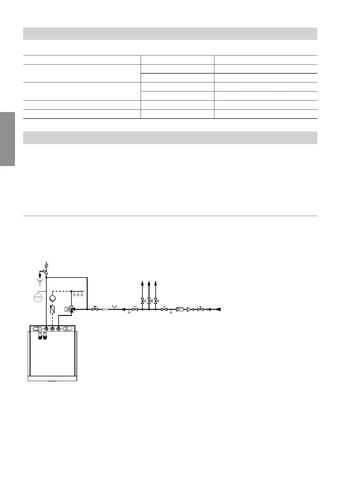
Fig. 24
A
Expansion vessel, suitable for drinking water
B
Visible discharge pipe outlet point
C
Safety valve
D
DHW circulation pump
E
Spring-loaded check valve
F
Automatic thermostatic mixing valve
G
DHW
H
Heat pump terminal area (plan view)
K
Shut-off valve
L
Flow regulating valve
M
Pressure gauge connection
N
Non-return valve/pipe separator
O
Drain valve
P
Cold water
R
Drinking water filter
S
Pressure reducer to DIN 1988-200:2012-05
Installation sequence
Connecting the refrigerant lines (cont.)
6199592
Installation