41
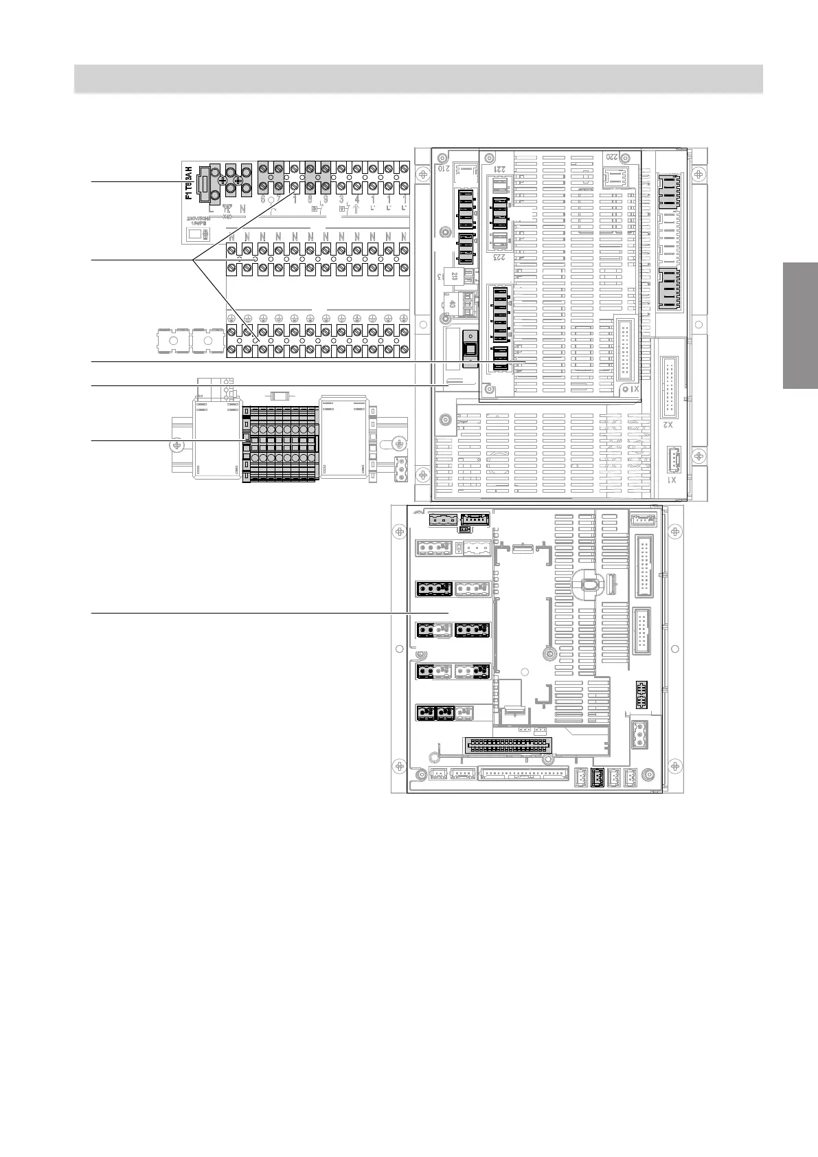
Indoor unit: Electrical terminal areas
F4
145
F0
X31
F16F14
211
224
225
216
214
241
J1
193A
F13
F11
G
212
X24
F12
X18
X1
X2
X3
222
F6
F3
E
A
B
C
D
F
Fig. 35
A
Heat pump control unit power supply 230 V~: See
page 52.
F1 Fuse 6.3 A (slow)
B
Luster terminals: See page 46.
X1 Terminals for protective conductors of all asso-
ciated system components
X2 Terminals for neutral conductors of all associ-
ated system components
C
Expansion PCB on main PCB: See page 44.
D
Main PCB: See page 42.
F3 Fuse 2.0 A (slow)
E
If available:
Switching module and power supply for instanta-
neous heating water heater: See page 53
onwards.
F
Controller and sensor PCB: See page 46.
Installation sequence
Electrical connection (cont.)
6199592
Installation