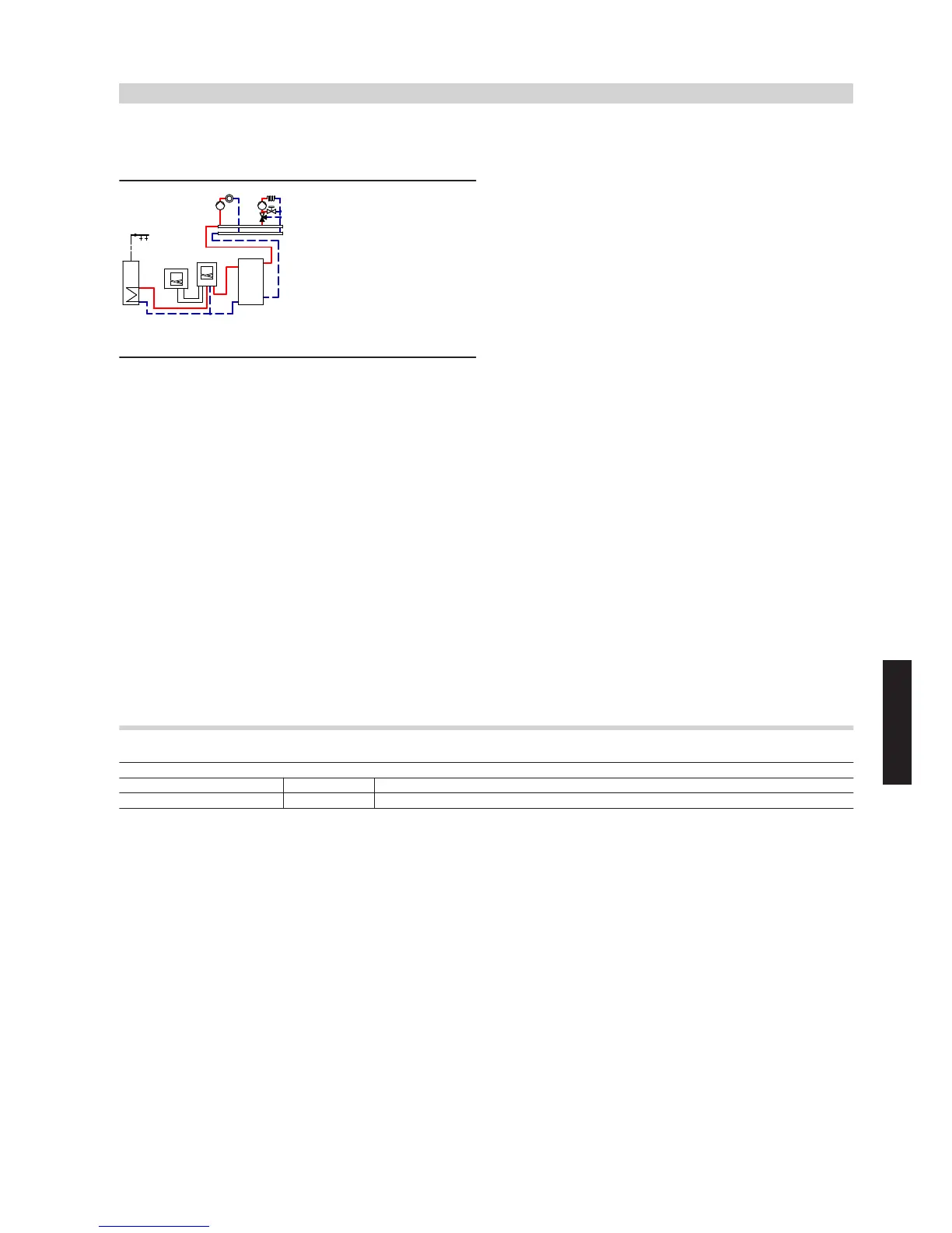
5.3 Vitocal 200-S, type AWB, one heating circuit without mixer, one heating circuit with
mixer, DHW heating and heating water buffer cylinder
ID: 4605358_1304_03
Application range
Detached houses with different utilisation patterns. Different sizing of
the heating circuits. Size the DHW cylinder in accordance with current
standards and requirements.
Main components
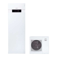
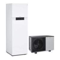
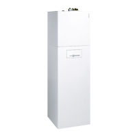
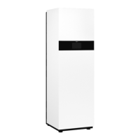
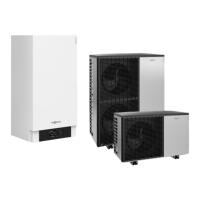
■ Vitocal 200-S, type AWB, with Vitotronic 200 control unit, type WO1C
■ Heating circuit distributor with one heating circuit without mixer and
one heating circuit with mixer (KM BUS)
■ DHW cylinder
■ Heating water buffer cylinder
Heating water buffer cylinder
The minimum flow rate of the heat pump is safeguarded via heating
water buffer cylinder
zP
and secondary pump
6
. It is possible to use
differential pressure-dependent heating circuit pumps
uZ
and
oZ
.
Central heating by heat pump
If the actual temperature captured by buffer temperature sensor
zQ
of
heating water buffer cylinder
zP
is lower than the set value selected
at the control unit, the heat pump, consisting of internal unit
1
and
external unit
wO
, starts. Heat pump
1
/
wO
supplies heating circuits
uP
/
oP
with heat via buffer cylinder
zP
.
Control unit 2 of heat pump wO regulates the heating water flow tem-
perature subject to the outside temperature.
Secondary pump
6
in the internal unit delivers the heating water via
3-way diverter valve
5
either to heating water buffer cylinder
zP
or
to DHW cylinder
eP
. Heating circuit pumps
uZ
and
oZ
deliver the
required water volume to the heating circuits. Any heat not absorbed
by the heating circuits is stored in heating water buffer cylinder
zP
.
Once the actual flow temperature value at the flow temperature sensor
inside internal unit
1
exceeds the set temperature selected at the
control unit, heat pump
1
/
wO
and secondary pump
6
are switched
off. Through the matched output of the inverter controlled compressor,
long runtimes of heat pump
1
/
wO
are achieved.
Heat pump
1
/
wO
restarts only when the temperature at upper tem-
perature sensor
zQ
of heating water buffer cylinder
zP
falls below the
set value. During the power-OFF period, the heating circuits will be
supplied with heat from heating water buffer cylinder
zP
.
DHW heating
In the delivered condition, DHW heating by heat pump
1
is given
priority over the heating circuits and takes precedence at night. The
heat demand is issued via cylinder temperature sensor
eQ
and control
unit
2
, which regulates secondary pump
6
and the internal 3-way
diverter valve. The control unit raises the flow temperature to the value
required for DHW heating.
Required parameter settings
ID: 4605358_1304_03
Parameter Value Function
7000 6 With heating circuit A1/HC1, M2/HC2, DHW cylinder
Vitocal 200-S/222-S/242-S
(cont.)
System examples
VIESMANN
135
5822 472 GB
5





 To Next Page