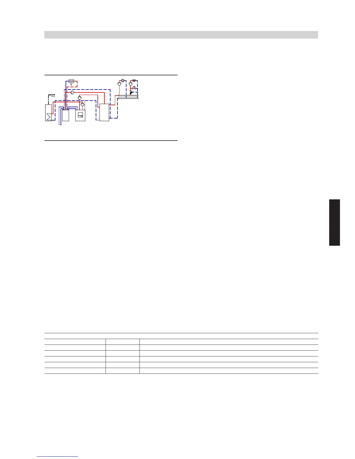
4.3 Vitocal 300-G/350-G with one heating circuit without mixer, one heating circuit with
mixer, DHW heating, heating water buffer cylinder and active cooling function via AC-Box
(2-pipe version), with fan convector
ID: 4605351_1304_03
Application range
Detached house with two heating circuits with different design layouts.
Size DHW cylinder
wP
in accordance with current standards and
requirements. Cooling via a separate cooling circuit e.g. in conjunction
with fan convectors
rE
.
Main components
■ Vitocal 300-G/350-G, type BW or BWC, up to 17 kW
■ Vitotronic 200, type WO1B
■ DHW cylinder
■ Heating water buffer cylinder
■ AC-Box
Heating water buffer cylinder
The minimum flow rate of heat pump
1
is safeguarded via heating
water buffer cylinder
eP
and secondary pump
6
. It is possible to use
differential pressure-dependent heating circuit pumps
tT
and
zE
.
Central heating by heat pump
Heat pump
1
, primary pump
5
and secondary pump
6
start when
the actual temperature captured by cylinder temperature sensor
eQ
of
heating water buffer cylinder
eP
falls below the set temperature selec-
ted at control unit
2
.
Control unit
2
regulates the heating water flow temperature. Subject
to demand, secondary pump
6
delivers heating water via heating
water buffer cylinder
eP
to the heating circuit, or via circulation pump
for cylinder heating
7
to DHW cylinder
wP
.
Type BWC:
Subject to demand, integral secondary pump
6
or circulation pump
for cylinder heating
7
delivers heating water either to the heating cir-
cuits or DHW cylinder
wP
.
Heating circuit pumps tT and zE deliver the required water volume to
the heating circuits. The flow rate in the heating circuit is regulated by
opening or closing the thermostatic radiator valves or the valves of the
underfloor heating distributor.
To balance the difference in energy between the primary and secon-
dary circuits, operate heating water buffer cylinder
eP
. Any heat not
absorbed by the heating circuits is stored in heating water buffer cyl-
inder
eP
. In addition, heat pump
1
achieves longer runtimes, and the
heating circuits are supplied with heat from heating water buffer cylin-
der
eP
during power-OFF periods.
DHW heating by heat pump
In the delivered condition, DHW heating by heat pump
1
is given
priority over the heating circuits and takes precedence at night.
The heat demand is issued via cylinder temperature sensor
wQ
and
control unit
2
, which controls circulation pump for cylinder heating
7
. The control unit raises the flow temperature to the value required
for DHW heating.
Type BWC:
The heat demand is issued via cylinder temperature sensor
wQ
and
control unit
2
, which controls integral circulation pump for cylinder
heating
7
.
The flow temperature can be raised above 60 °C with instantaneous
heating water heater
4
.
Active cooling function via AC-Box
The building can be cooled with heat pump control unit
2
in conjunc-
tion with AC-Box
qZ
(accessories). The natural cooling function is
enabled by control unit
2
for the cooling circuit as soon as the thresh-
old temperature (cooling limit temperature) that can be selected at
control unit
2
is exceeded. The valves in the AC-Box are set to natural
cooling. Heat is extracted from the cooling circuit and transferred to
the ground. If the cooling capacity is insufficient, the internal valves in
the AC-Box are set to active cooling and heat pump
1
starts. This
causes heat to be extracted from cooling circuit
rP
, and transferred
via heat pump
1
to consumer groups
wP
,
eP
,
tP
and
zP
. If there is
no consumer demand, the heat is transferred to the ground via probe
qW
.
Required parameter settings
ID: 4605351_1304_03
Parameter Value Function
7000 6 With heating circuit A1/HC1, M2/HC2, DHW cylinder
7100 3 Active cooling
7101 4 Cooling via separate cooling circuit
7104 50 Influence room temperature hook-up cooling circuit
7111 4 Cooling curve slope
Vitocal 300-G/350-G
(cont.)
System examples
VIESMANN
81
5822 472 GB
4