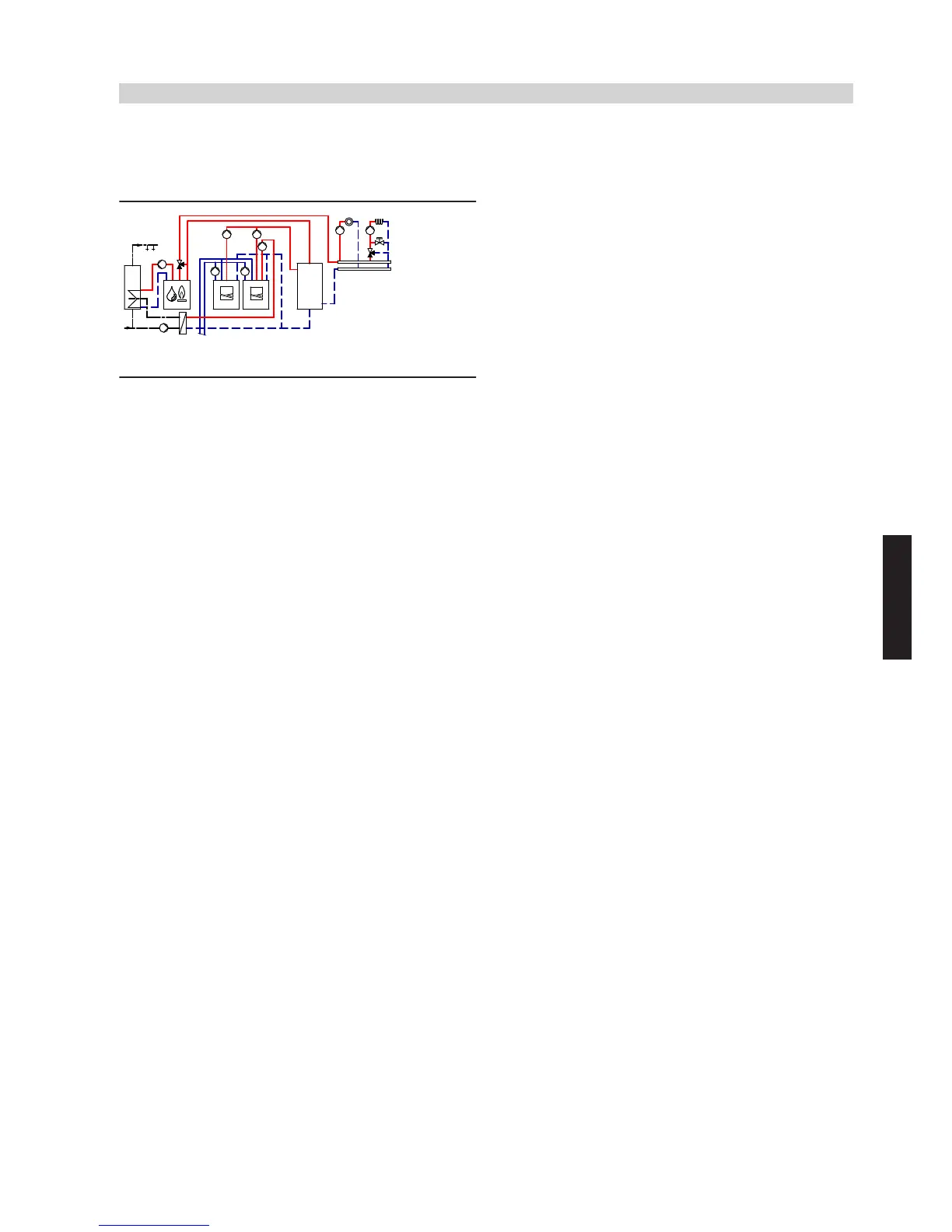
4.9 Vitocal 300-G/350-G, two-stage, one heating circuit without mixer, one heating circuit
with mixer, DHW heating, heating water buffer cylinder and external heat source (dual
mode parallel operation)
ID: 4605357_1304_04
Application range
Apartment building and buildings for commercial use with two different
heating circuits. Size DHW cylinder
eP
in accordance with current
standards and requirements.
Main components
■ Vitocal 300/350-G, type BW or BWS
■ Vitotronic 200, type WO1B
■ Heating circuit distributor with one heating circuit without mixer and
one heating circuit with mixer
■ DHW cylinder
■ Heating water buffer cylinder
■ External heat source
Heating water buffer cylinder
The minimum flow rate of heat pump stages
1
/
9
is safeguarded via
heating water buffer cylinder
zP
and secondary pumps
6
/
qP
. It is
possible to use differential pressure-dependent heating circuit pumps
uZ
and
oZ
.
Central heating by heat pump
Heat pump
1
and secondary pump
6
start when the actual tem-
perature captured by buffer temperature sensor
zQ
falls below the set
temperature selected at control unit
2
.
If the output from stage 1 is insufficient, stage 2
9
as well as primary
pump
wT
and secondary pump
qP
are also started to raise the heating
output.
Control unit
2
regulates the flow temperature in the secondary circuit
and thereby the heating circuit. Secondary pumps
6
/
qP
deliver the
heating water to heating water buffer cylinder
zP
. Heat pump stages
1
/
9
with primary pumps
5
/
wT
and secondary pumps
6
/
qP
stop
when the set return temperature is reached. Heating circuit pumps
uZ
and
oZ
deliver the required water volume to the heating circuits.
The heating circuit flow rate is regulated by opening and closing the
thermostatic radiator valves or the underfloor distributor valves and/or
through an external heating circuit control unit.
To balance the difference in water volume between the primary and
secondary circuits, operate heating water buffer cylinder
zP
in parallel
to the heating circuits. Any heat not absorbed by the heating circuits
is stored in heating water buffer cylinder
zP
. In addition, heat pump
stages
1
/
9
achieve longer runtimes.
Both stages
1
/
9
of the heat pump will restart when the temperature
at temperature sensor
zQ
in heating water buffer cylinder
zP
falls
below the set value.
During the power-OFF period, the heating circuits will be supplied with
heat from heating water buffer cylinder
zP
.
DHW heating by heat pump
In the delivered condition, DHW heating by heat pump stage
1
is
given priority over the heating circuit and takes precedence at night.
The heat demand is issued via upper cylinder temperature sensor
eW
and control unit
2
, which controls the circulation pump for cylinder
heating
7
, cylinder loading pump
eE
and motorised 2-way valve
eZ
.
Control unit
2
raises the flow temperature to the value required for
DHW heating.
The cylinder temperature can be raised above 60 °C with external heat
source
tP
.
Central heating with an external heat source
If the heat pumps are unable to maintain the required flow temperature
(captured by flow temperature sensor
zW
), external heat source
tP
is
requested. The external heat source starts; mixer
tR
initially remains
closed towards the heating circuit. Mixer
tR
opens towards the heating
circuit only when the required flow temperature has been reached at
boiler water temperature sensor
tE
. Mixer
tR
closes towards the
heating circuit when the required flow temperature has been achieved.
External heat source
tP
is shut down when the flow temperature (cap-
tured by
zW
), with mixer
tR
closed towards the heating circuit, no lon-
ger falls below an adjustable threshold for a given period (i.e. there is
either no longer any heat demand or heat pump
1
/
9
is supplying
adequate heat).
Note
The system example is only applicable in conjunction with modulating
boilers without lower temperature limit.
Match the heating curve of the external heat source to the heating
curve of the heating circuit with the highest flow temperature. Depend-
ing on the system scope and layout, we recommend that these are
offset upwards in parallel.
Vitocal 300-G/350-G
(cont.)
System examples
VIESMANN
115
5822 472 GB
4
 Loading...