L Temperature sensor at the heat
exchanger of the external unit
M Compressor temperature sensor
N Outside temperature sensor
O Suction gas temperature sensors
at the EEV A, B, C
*
1
and D
P Control PCB
R Accessory connections
1 Night mode switch
2 Standby mode switch
3 Economy mode switch
4 Default mode switch (1 = heat-
ing, 0 = cooling)
5 Fault message output, max.
230 V~, 1 A
6 MegaTool (not available)
S Programming unit PCB
T Choke coil
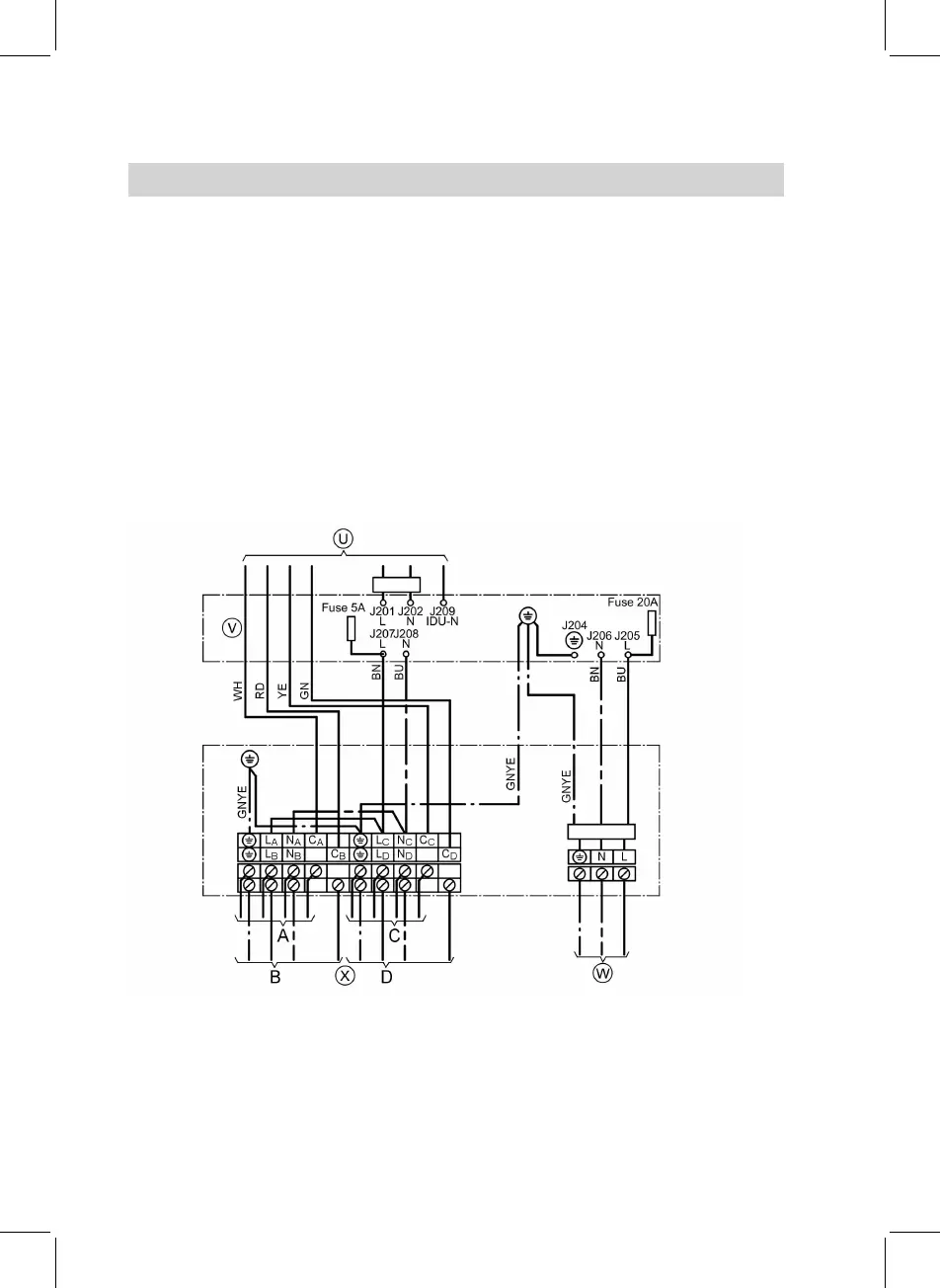
U Connection to the EMI filter PCB
(see page 46)
U Connection to the power supply
PCB (see page 45)
V EMI filter PCB
*
2
W Power supply, 230 V~, 50 Hz
X Connection with the internal
devices A, B, C
*
1
and D


 To Next Page