ViewSonic CLED5500 9
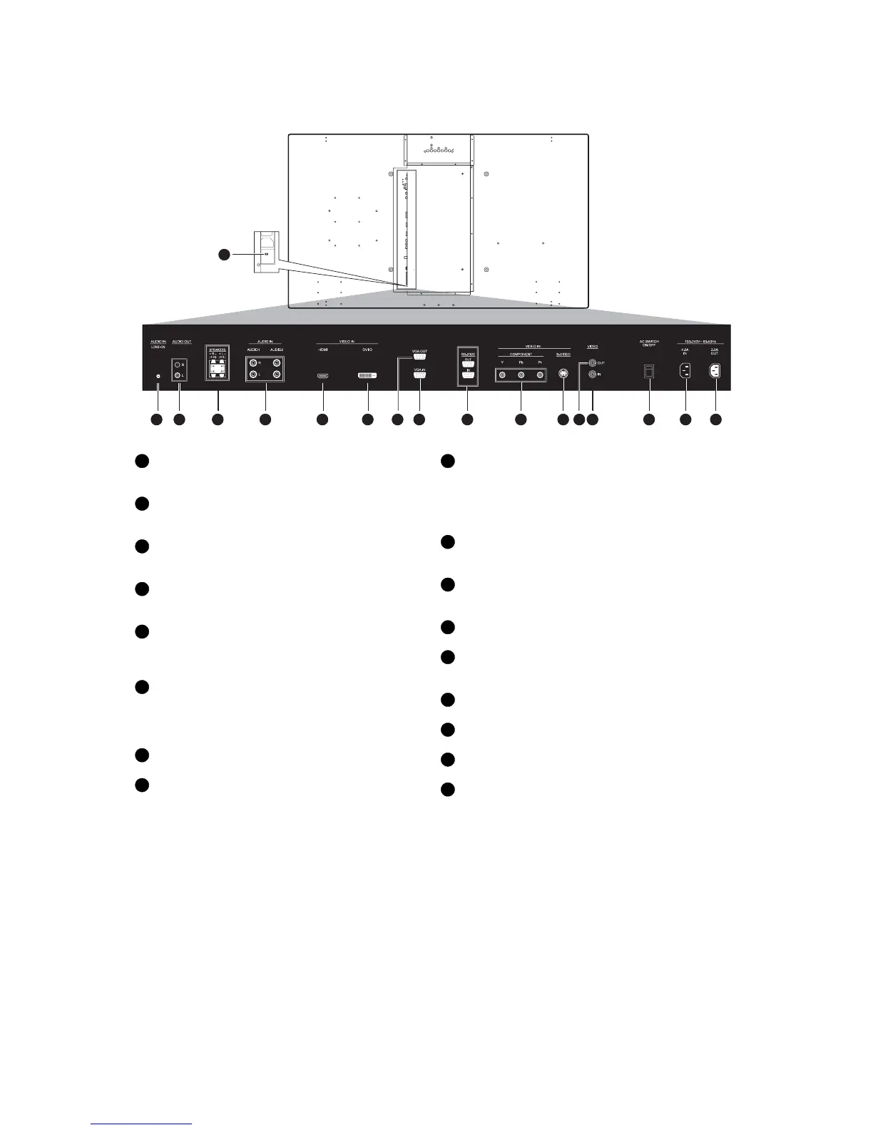
Terminal Panel
1 2 3 4 5 6 7 8 9
10 11 12 13 14 15 16
17
LINE-IN
To input audio signals from external equipment such
as a computer.
AUDIO OUT
To output audio signals from the LINE-IN, AUDIO IN
or HDMI jacks.
SPEAKERS (8 Ω, 12W x 2)
To output audio signals for external speakers from
the LINE-IN, AUDIO IN or HDMI jacks.
AUDIO IN R/L (AUDIO1/AUDIO2)
To input audio signals from external equipment such
as a VCR or DVD player.
HDMI
To input digital RGB signals from a computer.
* This connector does not support analog input.
Audio is supported via HDMI.
DVI-D
To input digital RGB signals from a computer.
*This connector does not support audio input. The
audio signal should be connected to the LINE-IN
jack.
VGA OUT (mini D-Sub 15 pin)
To output signals from VGA IN.
VGA IN (mini D-Sub 15 pin)
To input analog RGB signals from a computer or
other RGB equipment.
External control (mini D-Sub 9 pin)
Connects to the RS-232C output connector of a
computer, or the RS-232C-OUT connector of a multi-
connected CLED5500 monitor.
Connect the RS-
232C-OUT connector to the RS-232C-IN connector of
another
CLED5500
monitor.
COMPONENT
Connects to equipment such as a DVD player, HDTV
device or Laser disc player.
S-VIDEO
Connects to equipment such as a VCR or DVD
player.
VIDEO-OUT (BNC type connector)
To output signals from VIDEO-IN.
VIDEO-IN (BNC type connector)
Connects to equipment such as a VCR or DVD
player.
Main power switch
Turns the LCD monitor’s main power on or off.
AC-IN (100-240VAC, 4.0A)
Connects to the supplied power cord.
AC-OUT (100-240VAC, 2.0A)
Outputs AC power to another CLED5500 monitor.
Kensington lock hole
For installing a Kensington-type security lock.
1
2
3
4
5
6
7
8
9
10
11
12
13
14
15
16
17