11
WALL INSTALLATION
EXTERIOR-POWER VENTILATOR
DEV900-EXTERIOR POWER VENTILATOR KIT
(900 CFM)
1. Choose a position on the outside wall. Min. 24”
(61.0cm) from ground may vary depending on local
codes or location. Make sure no wall studs, pipes or
wires run through the opening area
2. Drill a guide hole at the center of the opening area.
3. From the outside, use the guide hole as a starting
point.
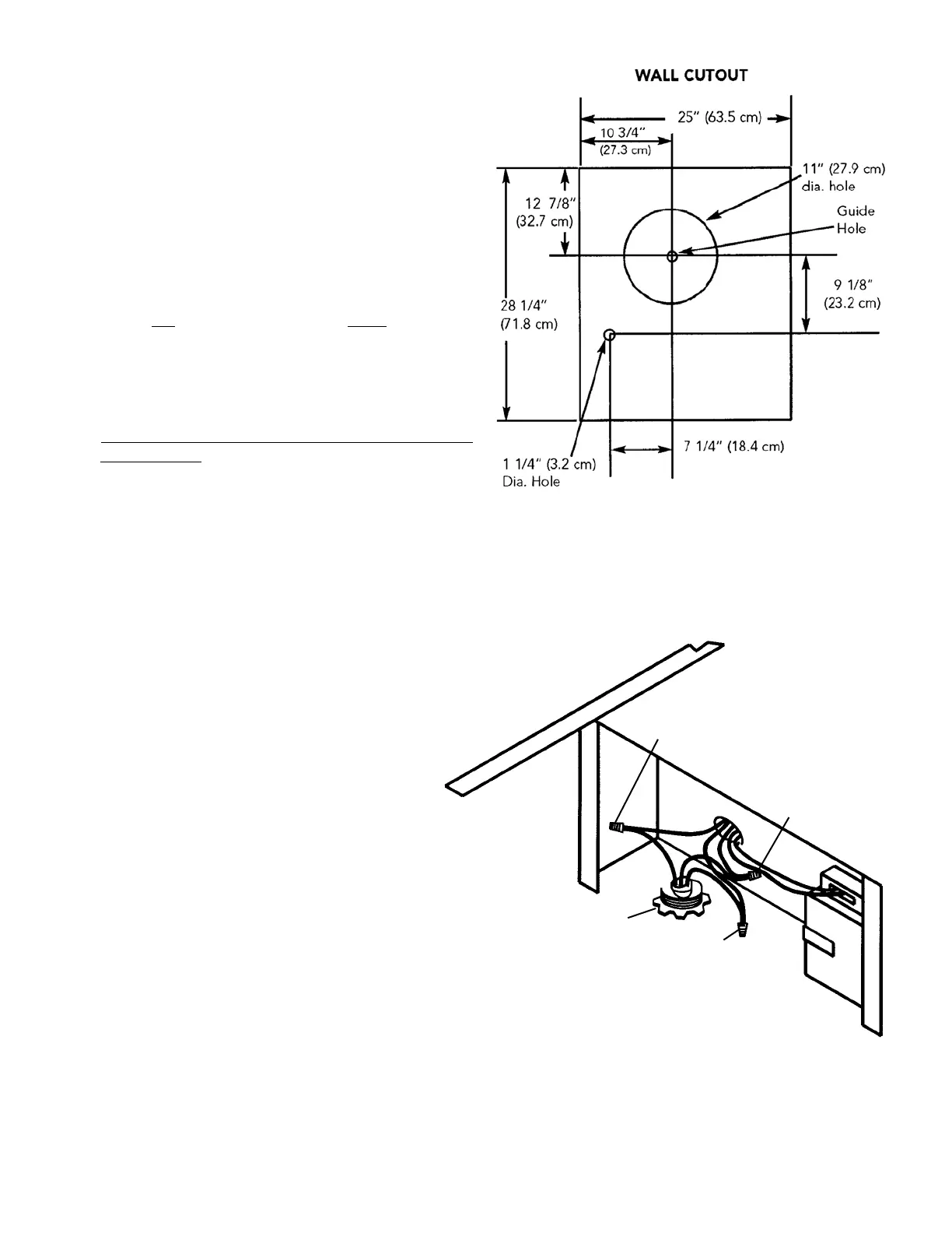
A. Use a T-square to measure 10 3/4” (27.3 cm) to
the left
of the guide hole, then down 12 7/8”
(32.7cm) to locate the top left corner of the
layout.
B. Starting from the top left corner, mark a 25” (63.5
cm) by 28 1/2” (72.4 cm) rectangle on the wall
located from guide hole.
4. Cut a r
ectangular hole in the siding only. Do not cut
the sheathing. Nail down all siding edges.
5. Mark an 11” (27.9 cm) diameter circle centered on
the guide hole and mark the center of the 1 1/4” (3.2
cm) diameter electrical wiring hole.
6. Cut the 11” (27.9 cm) hole in the sheathing and drill
the 1 1/4” (3.2 cm) as marked.
7. Place a large bead of caulk on the back side of the
housing along the outer edge
8. Center the blower ring in the 11” (27.9 cm) diameter
hole, making sure that the 1 1/4” (3.2 cm)
diameter electrical wiring hold aligns with the
hole in the wiring box.
9. Attach the blower to the roof with the six
screws provided. It is recommended that the
screws be located inside the blower housing.
All six holes in the back panel must be filled, or
any moisture that may get inside the housing
could leak into the house.
10. Using a good grade of roofing cement, seal all
the mounting screws.
11. Bring electrical wiring through the hole in the
wiring box and secure it according to local
codes.
12. Make the electrical connections with the proper
connector for the type of wiring being used.
Connect white to white, black to black, and
green or bare wire to green.
13. Replace wiring box cover and screws. Do not
pinch wiring under the cover.
14. Check for free movement of the damper before
installing housing cover and screws.
15. Turn on power and check operation of the blower.
16. Top and side flanges of the back plate may be
covered with trim strips. Do not block grill opening
at bottom with trim. It will adversely affect
performance of the blower.
Black
to
Black
120 VAC
Line in
White
to
White
Green to
Green
 Loading...