Do you have a question about the Viking VMOR205SS and is the answer not in the manual?
Steps to take before starting any servicing on an operative unit.
Warning about high voltage hazards present in the microwave oven.
Test procedure for leakage with oven enclosure installed.
Test procedure for leakage with oven enclosure removed.
Step-by-step explanation of the oven's operational sequence.
Instructions and warnings related to proper grounding of the appliance.
Step-by-step explanation of the oven's operational sequence.
How to use the variable power cooking feature.
Details on convection cooking modes and preheating.
Steps and conditions for preheating in convection mode.
How to use automatic mix cooking modes for combined cooking.
Explanation of the sensor cooking feature and its operation.
Details on convection broil, roast, and bake functions.
Instructions for using the timed defrost function.
Information about the fire sensing feature.
Description of the vertical venting method for hot air exhaust.
Description of the horizontal venting method for hot air exhaust.
Description of the re-circulation (inside venting) method.
Schematic diagram of the oven in the off condition.
Schematic diagram for microwave cooking operation.
Schematic diagram for convection cooking operation.
Schematic diagram for automatic mix cooking.
Explanation of how the oven door opening mechanism works.
Function of door interlock and sensing switches.
Function of the monitor switch and its role in safety.
Description and function of the temperature fuse.
Function of the thermal cut-out for the hood fan.
Description of the turntable motor's function.
Description of the cooling fan motor's function.
Description of the hood fan motor's function.
Function of the stirrer motor.
Function of the hood lamps.
Function of the heating element.
Explanation of how the convection cooking system works.
Explanation of the damper mechanism's operation.
Procedure for testing the magnetron assembly.
Procedure for testing microwave output power using water.
Procedure for testing the power transformer.
Procedure for testing the high voltage rectifier.
Procedure for testing the high voltage capacitor.
Testing of door interlock and sensing switches.
Testing the door sensing switch.
Testing the primary interlock relay (RY2).
Testing the monitor switch.
Testing the damper switch.
Procedure for testing and replacing a blown monitor fuse.
Testing the temperature fuse for the magnetron.
Testing the hood thermal cut-out.
Testing the thermistor.
Procedure for testing the hood fan motor.
Procedure for testing the damper motor.
Procedure for testing the heating element.
Checking temperature readings in convection mode.
Testing the various relays in the oven circuit.
Testing the timed defrost function.
Testing the noise filter.
Testing the key unit of the touch control panel.
Testing the control unit of the touch control panel.
Testing the key unit of the touch control panel.
Description of the key unit's composition and function.
Description of the control unit's components and functions.
Description of the physical structure of the humidity sensor.
Explanation of the operational principles of the humidity sensor.
Description of the circuit detecting the humidity sensor output.
Precautions for handling sensitive electronic components like CMOS LSI.
Illustrations of common electronic components.
Procedures and precautions for servicing the touch control panel.
Procedure for removing the hood exhaust louver.
Procedure for removing the entire oven from the wall.
Procedure for removing the outer case of the oven.
Removal of unit mounting screws and hood intake duct R.
Procedure for removing the power transformer.
Removal of hood fan motor, exhaust duct, lamp socket, and AH sensor.
Procedure for removing the magnetron.
Removal of high voltage rectifier and capacitor.
Procedure for removing the hood fan thermal cut-out.
Procedure for removing the magnetron temperature fuse.
Procedure for removing the cooling fan motor.
Procedure for removing the turntable motor and coupling.
Procedure for removing the stirrer motor.
Installation of stirrer cover and stirrer fan.
Procedure for removing the noise filter.
Procedure for removing the oven lamp.
Removal of control panel, control unit, and key unit.
Procedure for removing positive lock connectors.
Procedure for removing the convection duct assembly.
Procedure for removing the thermistor.
Procedure for removing the convection heater.
Procedure for removing the convection fan and motor.
Removal of damper motor and damper switch.
Removal of door sensing, interlock, and monitor switches.
Procedure for removing the door assembly.
Procedure for re-installing the door assembly.
Steps for disassembling the oven door.
Procedure for removing the choke cover from the door.
Procedure for removing the door frame.
List of electrical components and their part numbers.
List of cabinet parts and their part numbers.
List of control panel parts and their part numbers.
List of oven parts and their corresponding part numbers.
List of door parts and their part numbers.
List of miscellaneous items and hardware.
List of screws, nuts, and washers used in the appliance.
| Capacity | 2.0 cu. ft. |
|---|---|
| Power | 1000 Watts |
| Control Type | Electronic |
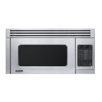
| Color | Stainless Steel |
| Cooking Levels | 10 |
| Child Lock | Yes |
| Warranty | 1 Year Limited |
| Type | Over-the-Range |
| Width | 29.875 inches |
| Exterior Dimensions | 29-7/8" W x 16-15/32" H x 15-15/32" D |