Do you have a question about the Villa Rotograph EVO D and is the answer not in the manual?
Explains icons used in the manual for notes and warnings.
Provides contact details for Villa Sistemi Medicali technical support.
General safety precautions for device operation, installation, and maintenance.
Details electromagnetic emissions compliance according to IEC 60601-1-2 standard.
Describes electromagnetic immunity standards and requirements for the device.
Guidelines for separation distances from RF transmitters to prevent interference.
Lists materials requiring proper disposal at the end of the unit's life.
Explains symbols used in the manual and on the device for safety and identification.
Details the various identification labels and laser symbols found on the device.
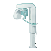
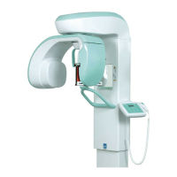
Describes device functions, versions, and optional packages like EVO XP and IMPLANT.
Provides a high-level overview of the system's main functional blocks.
Explains the functions of the device's control panel keyboard and display.
Lists the safety regulations and standards the device complies with.
Presents graphical data on the tube's load and anode cooling characteristics.
Details methods for measuring exposure parameters like kV and mA.
Outlines the procedure for verifying exposure parameters using a non-invasive method.
Provides the physical dimensions of the device in different versions.
Specifies electrical requirements, supply, grounding, and connection procedures.
Details the contents, packing dimensions, and weights for different device versions.
Specifies minimum room size and clearances required for installation.
Instructions for mounting the device to a wall, including bracket placement.
Steps for assembling the main column unit, including removing packaging.
Procedures for attaching the rotating arm assembly to the column.
Instructions for installing the optional Cephalometric arm kit.
Details the process of attaching the device's protective covers.
Steps for correctly inserting the digital sensor into its holder.
Steps for installing and configuring the necessary software on the PC.
Lists specialized tools required for system calibration and checks.
Procedures for verifying and adjusting the alignment of device components.
Procedures for calibrating the digital X-ray detectors.
Method for verifying exposure time parameters using invasive and non-invasive checks.
Instructions on how to save and modify automatic exposure settings.
Explains the function of LEDs on Generator and CPU boards and their troubleshooting significance.
Lists and explains different messages displayed by the unit during operation and errors.
Overview of the dedicated service programs accessible via passwords for system configuration and maintenance.
Identifies and provides solutions for defects in dental radiographies.
Provides detailed analysis of common problems found in panoramic examinations.
Provides the overall system block diagram.
Shows the physical layout and circuit diagram for the Column CPU PCB A1.
Shows the physical layout of the Touch Screen Control PCB A4.
Shows the physical layout and circuit diagram for the CPU PCB A5.
Shows the physical layout and circuit diagram for the Microprocessor PCB A6.
Shows the layout and circuit diagram for the Rotation Group PCB A7.
Shows the layout and circuit diagram for the Generator CPU PCB A9.
Shows the layout and circuit diagram for the Generator PCB A10.
Shows the layout and circuit diagram for the CEPH arm connection PCB A12.
Shows the layout and circuit diagram for the Sensor power PCB A21.
Lists spare parts for the column section, including electrical and mechanical parts.
Lists spare parts for the upper movement assembly, including cables.
Lists spare parts for the rotation arm, including the tubehead and boards.
Lists spare parts for the Ceph device, including sensors, motors, and belts.
Lists all external covers for the device.
Lists accessories, consumables, and specialized tools for operation and maintenance.
A table for recording factory and new settings for various device parameters.
| Brand | Villa |
|---|---|
| Model | Rotograph EVO D |
| Category | Medical Equipment |
| Language | English |