Do you have a question about the Vimar ELVOX 6591 and is the answer not in the manual?
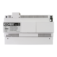
Module switches audio, video, and lock functions for two camera entrance panels.
Device dimensions with protective covers inserted are 208x135x72 mm.
The last call takes priority, excluding operation of other camera panels when a call is made.
Installation must comply with prevailing electrical system regulations in the country of installation.
Compliance with EMC directive, specifically EN 61000-6-1 and EN 61000-6-3.
Dispose of appliance separately from municipal waste as per WEEE directive to protect environment and health.
Identifies components like entrance panels, locks, cameras, power supplies, and switching modules with their part numbers.
Instructions for inserting a 75 Ohm termination resistor into the last monitor between terminals V2-M.
Guidance on resolving humming sound by setting the A-B slide switch to position 'A'.
Reference to instructions for alternative connection variants with power supplies Art. 6580-6581-6680-6681.
Lists compatible entrance panel series (e.g., 8000, 3300, 1200) for the system.
Visual representation of how monitors, power supplies, and the switching module connect within the system.
Detailed electrical schematic showing components, their values, and interconnections.
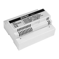
Information on connecting the switching module to various compatible power supply units.