EasyManua.ls Logo

Vimar Plana - User Manual

Vimar Plana
3 pages
Print Icon
To Next Page IconTo Next Page
Loading...
Viale Vicenza 14
36063 Marostica VI - Italy
www.vimar.com
20592.0 01 2105
EIKON
20592.0
ARKE'
19592.0-19592
IDEA
16492
PLANA
14592-14592.0
Connected 2-way switch
20592.0-19592.0-14592.0: to be completed with 1- or 2-module interchangeable buttons.
19592-16492-14592: complete with button.
The device is equipped with 2 interlocked relay outputs for the switch function and it can also be
connected to existing wired multi-way/two-way switches to make the load function “connected”.
TWO OPERATING MODES (ALTERNATIVE)
or
Download the View Wireless App from the stores onto the tablet/smartphone you
will be using for configuration.
Depending on the mode you select, you will need:
Gateway
art. 20597-19597-16497-14597
Zigbee Gateway
(Amazon Echo Plus, Echo Show or Echo
Studio)
Alexa App
View App
for management via smartphone/tablet
Amazon Alexa, Google Assistant, Siri and
Homekit voice assistants for possible
voice operation
CONFIGURATION IN
1. Create your Installer account on MyVimar (on-line).
2. Wire all the devices in the system (2-way switches, actuators, thermostats, gateway, etc.).
3. Start the View Wireless App and log in with the credentials you just created.
4. Create the system and the environments.
5. Associate all the devices with the environments, except for the gateway (which should be
associated last).
To associate the 2-way switch:
• Select “Add” (
), choose the environment to place it and give it a name
• Select ; activate the Bluetooth connection on your tablet/smartphone and approach the
2-way switch
Press the button on the 2-way switch and set the desired function
6.
For every device, set the function, the parameters and any accessory devices (wired or radio
control and related function).
7. Transfer the configuration of the devices to the gateway and connect it to the Wi-Fi network.
8. Transfer the system to the Administrator user (who must have created his/her profile on
MyVimar).
For details please refer to the View Wireless App manual you can download from www.
vimar.com DOWNLOAD View Wireless MOBILE App
CONFIGURATION IN
Follow the procedure above from points 1 to 3.
Associate the 2-way switch directly with Amazon Echo Plus, Echo Show or Echo Studio.
1) Press the button on the 2-way switch until the LED flashes. Download the Zigbee software
onto the device using the View Wireless App (see the View Wireless App manual).
To update the software on the device, the procedure is the same.
2) After conversion to Zigbee technology (or the software update), the 2-way switch automatically
goes into pairing mode so that it can be recognised by the Amazon device within 5 minutes.
If the 2-way switch is not in pairing mode, cut off the power supply and restore it after a few
seconds.
3) Associate the 2-way switch with Amazon Echo Plus, Echo Show or Echo Studio according to
the procedure envisaged by the voice assistant (see the Amazon documentation).
Set the actuator parameters.
1) Within the first 5 minutes after the device has been powered (already associated with Amazon
Alexa), press the button for 15 s; this way, you can select the relay operation - between one-po-
sition stable and two-position stable (the LED flashes green for the two-position stable setting
and amber for the one-position stable setting).
2) Briefly press the button to switch from two-position stable to one-position stable and vice
versa; once the choice has been made, press the button for 5 s to confirm. If you have set the
two-position stable setting, the LED flashes green three times, whereas if you have chosen the
one-position stable setting, you will move on to the next step (3).
3) Press the button for 5 s to set the one-position stable activation time. Press the button briefly,
the output is activated and the LED lights up amber permanently; at the end of the time you
wish to set, press the button again. The output is deactivated and the LED flashes amber for 3
times to confirm the setting made.
N.B. When the voltage returns after a power outage, the relay maintains the state in which it was
prior to the power supply cut out.
Summary of Zigbee technology mode signalling.
• During normal operation:
LED Meaning
On
(amber for Eikon, blue for Arké, green for Idea and
Plana)
Relay active
Off Relay not active
• In the configuration phase:
LED Meaning
Flashing white
(for max 5 min.)
Zigbee mode active pending voice assistant
Flashing blue
(for max 2 min.)
Pending receipt of a fw update
Blue permanently lit
Device associated with the smartphone via
Bluetooth
Flashing green during the one-position
stable/two-position stable configuration
(for max 5 min.)
Setting in two-position stable
Flashing amber during the one-position
stable/two-position stable configuration
(for max 5 min.)
Setting in one-position stable
Amber permanently lit One-position stable time setting
Flashing green 3 times Confirms two-position stable setting
Flashing amber 3 times Confirms one-position stable setting
Flashing green quickly 3 times
Device correctly associated with the voice
assistant
On
(amber for Eikon, blue for Arké, green for
Idea and Plana)
Relay active during normal operation
CONTROLLABLE LOADS.
For correct load state signalling, connect a 2 W minimum load.
Loads
- maximum
100 V~ 250 W 50 W 60 W 125 VA
240 V~ 500 W 100 W 120 W 250 VA
RESETTING THE DEVICE.
The reset restores the factory settings. Within the first 5 minutes from powering, press the
button for 30 s until the white LED flashes.
INSTALLATION RULES.
• Installation must be carried out by qualified persons in compliance with the current regula-
tions regarding the installation of electrical equipment in the country where the products are
installed.
• The device must be completed with interchangeable buttons and installed in flush mounting
boxes or surface mounting boxes with Eikon, Arkè and Plana mounting frames and cover
plates.
• The relay output power circuit must be protected against overloads by installing a device, fuse
or automatic 1-way switch, with a rated current not exceeding 10 A.
• Installation must be carried out with the system switched off. Install the buttons onto the
switch mechanism before powering up the system.
IMPORTANT: the electronic switch must be powered with the same L and N that power
the load. In the event of installation with wired multi-way/two-way switches, the electronic
switch should be connected so that it is always powered and therefore should be installed
instead of the wired two-way switch furthest from the load.
CHARACTERISTICS.
Rated supply voltage: 100-240 V~, 50/60 Hz.
Dissipated power: 0.55 W
• RF transmission power: < 100mW (20dBm)
• Frequency range: 2400-2483.5 MHz
Terminals:
- 2 terminals (L and N) for line and neutral
- 1 terminal (P) for connection to the remote wired control (for instance art. 20008-19008-
16080-14008). The max distance between the IoT device and the push button is 50 m
with a cable with a minimum cross-section of 1.5 mm
2
.

Other manuals for Vimar Plana

Question and Answer IconNeed help?

Do you have a question about the Vimar Plana and is the answer not in the manual?

Summary

Connected 2-way Switch Overview

Two Operating Modes

Describes the two main operating modes: Bluetooth and Zigbee, for device configuration and control.

Zigbee Technology Mode Signalling

Details LED status indicators for Zigbee operation, including normal and configuration phases.

Controllable Loads

Specifies minimum load requirements for correct operation and load state signalling.

Resetting the Device

Provides instructions on how to restore the device to its original factory settings.

Installation Rules

Key guidelines for safe and compliant installation by qualified personnel.

Technical Characteristics

Lists essential technical specifications like rated voltage, power consumption, RF power, and frequency.

Bluetooth Operation and Settings

Bluetooth Operation Mode

Explains how the device functions in Bluetooth mode and its capabilities with accessories.

Configurable Settings

Details parameters adjustable via the View Wireless App, including LED backlighting and relay operation.

Regulatory Compliance

Lists relevant directives, standards, and compliance declarations for the product.

Front and Back View

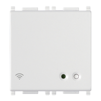
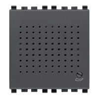
Illustrates the physical layout and connection points of the device.

Wiring Connections

Individual Lighting Device Connection

Shows a basic wiring diagram for connecting an individual lighting device.

Circuit with Push Buttons and Relays

Illustrates wiring examples for circuits using push buttons, relays, and switches.

Two-Way Switch with Push Buttons

Demonstrates a two-way switch setup with traditional push buttons for lighting.

Overview

This document describes the Vimar Connected 2-way switch, a versatile device designed to integrate into modern smart home systems, offering both Bluetooth and Zigbee connectivity options. The switch is intended to be completed with 1- or 2-module interchangeable buttons and is equipped with two interlocked relay outputs for its primary switching function. It can also be connected to existing wired multi-way/two-way switches, allowing for the integration of traditional setups into a "connected" smart home environment.

Function Description

The Connected 2-way switch serves as a control point for lighting and other loads, enabling both local and remote operation. It supports two main operating modes: Bluetooth technology and Zigbee technology, providing flexibility in how it integrates into a smart home ecosystem.

In Bluetooth technology mode, the device operates by default and allows for several functionalities. Users can recall scenarios involving lights, roller shutters, or socket outlets within the system. It can also be associated with radio control devices (e.g., Vimar art. 03925) to control the on-board actuator or recall a scenario. When used with a Vimar gateway (e.g., art. 20597-19597-16497-14597), the switch's functions can be managed locally or remotely via the View App. This mode also enables control via popular voice assistants like Amazon Alexa, Google Assistant, and Siri, and is compatible with Apple HomeKit. From firmware version 1.7.0 onwards, the device also functions as a repeater node for battery-operated devices (e.g., Vimar art. 03980), extending the range and reliability of the Bluetooth network.

In Zigbee technology mode, the switch can be directly associated with Zigbee gateways such as Amazon Echo Plus, Echo Show, or Echo Studio. This allows for integration into Zigbee-based smart home systems and control through the Alexa App.

The device features a front button that serves a dual purpose: controlling the connected load and acting as a configuration push button. An RGB LED provides visual feedback on the load status (customizable via the View Wireless App) and the configuration status (indicated by flashing blue).

Usage Features

The setup process for the Connected 2-way switch varies slightly depending on the chosen operating mode.

For Bluetooth configuration:

  1. Users must first create an Installer account on MyVimar (online).
  2. All devices in the system (including 2-way switches, actuators, thermostats, and gateways) should be wired.
  3. The View Wireless App is then launched, and the user logs in with their credentials.
  4. The system and its environments are created within the app.
  5. Devices are associated with their respective environments, with the gateway being associated last. To associate the 2-way switch, users select "Add" (+) in the app, choose the environment, and give it a name. They then activate Bluetooth on their tablet/smartphone, approach the 2-way switch, press its button, and set the desired function.
  6. For each device, users can set its function, parameters, and any accessory devices (wired or radio control).
  7. The configuration is then transferred to the gateway and connected to the Wi-Fi network.
  8. Finally, the system is transferred to an Administrator user (who must have created a profile on MyVimar).

For Zigbee configuration: The initial steps (1-3) are similar to Bluetooth configuration. The 2-way switch is then directly associated with Amazon Echo Plus, Echo Show, or Echo Studio.

  1. To initiate pairing, the button on the 2-way switch is pressed until the LED flashes. The Zigbee software is downloaded onto the device using the View Wireless App. If the 2-way switch is not in pairing mode, cutting off and restoring power can re-enable it.
  2. After conversion to Zigbee technology or a software update, the 2-way switch automatically enters pairing mode for up to 5 minutes to be recognized by the Amazon device.
  3. The 2-way switch is associated with the Amazon Echo device following the voice assistant's documentation.

Setting actuator parameters in Zigbee mode:

  1. Within 5 minutes of powering the device (after association with Amazon Alexa), pressing the button for 15 seconds allows selection of relay operation: one-position stable or two-position stable. The LED flashes green for two-position stable and amber for one-position stable.
  2. Briefly pressing the button toggles between these two modes. Once the choice is made, pressing the button for 5 seconds confirms it. The LED flashes green three times for two-position stable or amber three times for one-position stable.
  3. For one-position stable mode, pressing the button for 5 seconds sets the activation time. Briefly pressing the button activates the output and lights the LED amber permanently. At the end of the desired time, pressing the button again deactivates the output, and the LED flashes amber three times to confirm the setting.

The device's LED signaling provides clear feedback on its status:

  • Normal operation (Zigbee mode): LED On (amber for Eikon, blue for Arké, green for Idea and Plana) indicates relay active; LED Off indicates relay not active.
  • Configuration phase:
    • Flashing white (max 5 min): Zigbee mode active, pending voice assistant.
    • Flashing blue (max 2 min): Pending receipt of a firmware update.
    • Blue permanently lit: Device associated with the smartphone via Bluetooth.
    • Flashing green during configuration (max 5 min): Setting in two-position stable.
    • Flashing amber during configuration (max 5 min): Setting in one-position stable.
    • Amber permanently lit: One-position stable time setting.
    • Flashing green 3 times: Confirms two-position stable setting.
    • Flashing amber 3 times: Confirms one-position stable setting.
    • Flashing green quickly 3 times: Device correctly associated with the voice assistant.
    • On (amber for Eikon, blue for Arké, green for Idea and Plana): Relay active during normal operation.

The View Wireless App offers several customizable settings:

  • RGB LED backlighting: Color can be selected from a default list (default: amber for Eikon, blue for Arké, green for Plana).
  • LED brightness: Off, low, medium, high for active load (default: high) and for off load (default: off).
  • Load status when voltage is restored: Off, on, or previous status (default: previous status).
  • Relay operation: Two-position stable or one-position stable (default: two-position stable).
  • One-position stable activation time: (default: 60 s).

Maintenance Features

Resetting the device: To restore factory settings, press the button for 30 seconds until the white LED flashes, within the first 5 minutes of powering the device.

Installation Rules:

  • Installation must be performed by qualified persons in compliance with local electrical equipment regulations.
  • The device requires interchangeable buttons and must be installed in flush or surface mounting boxes with appropriate Vimar mounting frames and cover plates.
  • The relay output power circuit must be protected against overloads by a device (fuse or automatic 1-way switch) with a rated current not exceeding 10 A.
  • Installation must be carried out with the system switched off. Buttons should be installed onto the switch mechanism before powering up the system.
  • It is crucial that the electronic switch is powered with the same Line (L) and Neutral (N) that power the load. In multi-way/two-way switch installations, the electronic switch should always be connected to a constant power supply and installed in place of the wired two-way switch furthest from the load.

Controllable Loads: For correct load state signaling, a minimum 2 W load must be connected. The maximum loads supported are:

  • 100 V~: 250 W, 50 W, 60 W, 125 VA
  • 240 V~: 500 W, 100 W, 120 W, 250 VA

Important Note: When voltage returns after a power outage, the relay maintains the state it was in prior to the power supply cut-out.

Vimar Plana Specifications

General IconGeneral
SeriesPlana
Mounting TypeFlush mounting
ColorWhite
Voltage230V
Current10A
TypeSwitch

Related product manuals