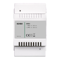
DESCRIPTION
Type 69RH for ELVOX 2-WIRE systems, is equipped with 2 relays
with normally open contacts, which can perform two dierent tasks
depending on the setting by the user entered by means of a simple
programming procedure. The two operating modes are:
1. RELAY MODE: relay for auxiliary services (no programming
needed)
2. REPEATER MODE: programmable call repeater (programming
required)
To identify whether the device has been set to repeater mode, or
not programmed i.e. set to relay mode, simply check the indicator
LED L1 on the printed circuit board on activation of the device:
LED OFF RELAY MODE
LED FLASHING FOR ONE SECOND REPEATER MODE
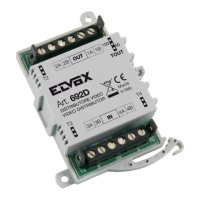
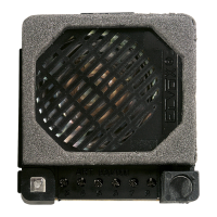
DESCRIPTION OF TERMINALS AND COMPONENTS (g. 1)
1, 2, B1, B2) BUS line (two pairs of terminals connected in
parallel).
1A, 1B) 1st normally open contact, maximum load 3A
230Vac.
2A, 2B) 2nd normally open contact, maximum load
3A 230Vac.
ACTIV. TIME 1) Adjustment trimmer for activation time of 1st
contact (RELAY mode).
ACTIV. TIME 2) Adjustment trimmer for activation time of 2nd
contact (RELAY mode).
IDO-ID1-ID2) Jumpers for device identication (RELAY
mode) or for group identification (RE-
PEATER mode).
S1) Pushbutton for group programming/deletion
(REPEATER mode).
L1) LED for checking operating status and for
group programming/deletion (REPEATER
mode).
ABC) jumpers for termination of BUS.
RELAY MODE
In this mode the two relays can be set for the activation of two
auxiliary functions from each interphone and monitor using ELVOX
2-WIRE TECHNOLOGY. The normally open contacts are inde-
pendent and can be timed from 1 to 30 seconds, by adjusting the
two trimmers on the printed circuit board (g. 1) marked with the
texts “ACTIV. TIME 1” and “ACTIV. TIME 2”.
Up to 8 device types 69RH can be connected on the ELVOX
2-WIRE system. This means that a total of 16 auxiliary functions
can be used (two relays for each device type 69RH). Each device
type 69RH must then be assigned with an identication code, by
setting jumpers ID0-ID1-ID2 on the printed circuit board (g. 1). To
assign the identication codes, refer to TAB.1 g. 2.
Activation of the auxiliary services is from the interphones and mon-
itors, and therefore refer to the instructions of the appliances in the
section on auxiliary services 1 and 2.
REPEATER MODE
In this mode the device repeater, combined with a ringtone type
860A or chime, enables repetition of the call made from a panel
or intercommunicating device and addressed to one or more in-
terphone or monitor groups (up to a maximum of 4 groups). The
device uses two separate relays for the repetition of calls from pan-
els and intercom devices, and therefore the ringtones can be dif-
ferentiated making the suitable connections to the ringtone device.
(see wiring diagrams).
PROGRAMMING REPEATER MODE
To activate 692H mode, the following settings must be entered to
set the groups for which call repetition is required (up to a maximum
of 4 groups). The programming procedure is as follows:
1. LED initially o and jumper on ID2.
2. Position the jumpers on ID0 and ID1 to select the group for call
repetition (tab. 1 and g. 2)
3. Press and hold the programming key for 2 seconds, until the
LED turns on, to enter PROGRAMMING MODE.
4. At this point the master of the group selected in point 2 must
be assigned. To do this, press any one of the lock pushbuttons
to activate the operator F1, F2, of the interphone/monitor to be
assigned as group master. On reception of the signal by the
remote device, the LED changes to ashing status.
5. To conrm memorisation of the address, pres the programming
key. The LED turns o and programming is complete.
6. To set another call group, proceed as described in points 2-5. A
maximum of 4 groups can be selected as required.
NOTES
• Point 4 must be completed within an interval of 2 minutes; oth-
erwise the system automatically exits programming mode (the
LED turns o), without memorising the data.
• Point 5 must be completed within an interval of 1 minute; oth-
erwise the system automatically exits programming mode (the
LED turns o), without memorising the data.
• As programming is write-only, the group masters cannot be
identied.
DELETING A GROUP
A previously programmed group can be deleted as follows:
1. LED L1 initially o.
2. Remove the jumper from ID2 (g. 1)
3. Position the jumpers ID0 and ID1 to enable selection of the call
group address to be deleted (tab1 and g. 2)
4. Press and hold the programming key for 2 seconds, until the
LED L1 turns on. This remains lit for one second, after which it
turns o to conrm deletion.
5. Repeat points 3 and 4 to delete other previously memorised
groups as required.
RETURN TO RELAY MODE
Once all groups have been deleted according to the procedure de-
scribed in the previous chapter, the device returns to 692R mode.
For conrmation, disconnect and reconnect the device 69RH to the
BUS and check the status of the LED.
LED L1 OFF RELAY MODE
LED FLASHING FOR ONE SECOND REPEATER MODE
The instruction manual is downloadable from the site www.
vimar.com
3
69RH
EN
 Loading...