13
K7559G.01
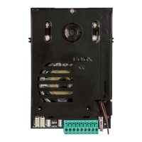
1 - USB connector for programming using SaveProg
software
2 - Connection terminal block
M = earth
FP =
for the “Alert” function. See the relevant paragraph in the
use and installation manual.
Note: the FP/M pair of terminals can also be used, when
use as “Alert” is not active, to simulate a call from Art.
6120 intended for the master with respect to any of its
secondary indoor stations.
Note: the maximum connection distance to the terminals
is 10 m.
1, 2 = Due Fili Plus Bus
SWITCH TABLE
A = the BUS cable enters terminals 1, 2 and continues
to another indoor station
B = The BUS cable with a characteristic impedance of
1, 2 and the riser stops in the indoor station.
C = The BUS cable with characteristic impedance of
terminals 1, 2 and the riser stops in the indoor station.
1 - Connecteur USB pour la programmation à partir du
logiciel SaveProg
2 - Bornier de connexion
M = Masse
FP =
est possible de l'utiliser comme entrée pour la fonction «
Alerte ». Consulter le paragraphe correspondant dans le
manuel d'installation et d'utilisation.
Remarque : les deux bornes FP/M peuvent également
être utilisées, lorsque la fonction « Alerte » n'est pas
activée, pour simuler un appel provenant de l’Art. 6120
et destiné au poste principal par rapport aux éventuels
postes intérieurs secondaires.
Remarque : la distance maximale des connexions aux
bornes correspond à 10 m.
1, 2 = Bus Due Fili Plus
3 - Dip-Switch d
TABLEAU SWITCH
A = Le câble du BUS arrive aux bornes 1, 2 et
continue vers un autre poste intérieur
B = Le câble BUS avec une impédance caractéristique
bornes 1, 2 et la colonne montante s'arrête au poste
intérieur
C = Le câble BUS ayant une impédance
paires torsadées) arrive aux bornes 1, 2 et la colonne
montante s'arrête au poste intérieur
1 - USB-Anschluss für Programmierung über die Software
SaveProg
2 - Anschlussklemmenleiste
M = Masse
FP =
für die Funktion "Warnmeldung" verwendet werden.
Siehe entsprechenden Abschnitt in der Installations- und
Bedienungsanleitung.
Hinweis: Das Klemmenpaar FP/M kann bei nicht
aktivierter Funktion "Warnmeldung" auch dazu
verwendet werden, einen von Art. 6120 an das Gruppen-
Hauptgerät gerichteten Ruf gegenüber seinen etwaigen
sekundären Innenstellen zu simulieren.
Hinweis: Die maximale Anschlusslänge an die Klemmen
beträgt 10m.
1, 2 = Bus Due Fili Plus
3 - Dip-Schalter f
SCHALTERTABELLE
A = Das BUS-Kabel tritt in die Klemmen 1, 2 ein und
führt und zu einer anderen Innenstelle weiter
B = Das BUS-Kabel mit typischer Impedanz 100 Ohm
ein und die Steigleitung endet an der Innenstelle
C = Das BUS-Kabel mit typischer Impedanz 50 Ohm
tritt in die Klemmen 1, 2 ein und die Steigleitung endet
an der Innenstelle
 Loading...