EasyManua.ls Logo

Vimar ELVOX 945B - User Manual

Vimar ELVOX 945B
24 pages
Print Icon
To Next Page IconTo Next Page
Loading...
945B, 945B/I
Porter’s Switchboard
Installer guide
Question and Answer IconNeed help?

Do you have a question about the Vimar ELVOX 945B and is the answer not in the manual?

Summary

Product Overview and Quick Guide

Display Management and Icons

Explains the display's division into zones and the meaning of various icons.

System Features and Management

Stored Calls and Event Logging

Details storing and managing incoming events like calls and function activations.

Internal Watch and Wake-Up Services

Describes the internal clock, date display, and programmable wake-up functions.

Keypad Security and Mode Switching

Covers software keypad lock and simplified internal/external mode switching.

Printer and PC Connectivity

Explains printer management and PC connection for configuration and data retrieval.

Switchboard Parameter Programming

Entry to Programming Mode

Details the procedure to enter the switchboard's programming mode via the keypad.

Switchboard Operation and Control

Displaying Time, Date, and Wake-Up

Instructions for viewing time, date, and programmed wake-up schedules on the display.

Activating Lock Release and Functions

How to activate door lock release and auxiliary functions (F1, F2, F6-F8) using the keypad.

Software Keypad Lock Operation

Procedures for locking and unlocking the switchboard keypad using a password.

Stored Calls Queue Management

How to view, scroll, and clear stored calls from the memory buffer.

Programming Menu Functions

Programming Commands to Store

Selects which commands are stored in the reception buffer for recall.

Programming Commands to Print

Selects which commands are sent to the printer for logging purposes.

Setting Wake Up Times

Configures the times for the two available daily wake-up services.

Setting Time and Date

Procedure for setting the current time and date on the switchboard.

Printing Activation and Configuration

Setting the Printer Type

Adapts printing output based on the specific type of connected printer.

Printer Paper Ejection and Advice

Instructions for forcing paper ejection and recommendations for suitable printers.

Melody Management and Technical Parameters

Melody Association and Playback

Explains melody assignments to events and how to play/limit them.

Downloading New Melodies

Describes methods for adding or copying new melodies into the switchboard.

Technical Parameter Definitions

Defines key technical parameters like entrance panel number, digit selection, and sound enable.

Switchboard Keypad Layout and Functions

Left and Right Hand Keypad Sections

Details the functions assigned to buttons in the left and right keypad sections.

Keypad Indicator Lamps

Explains the meaning of the indicator lamps located in the central keypad section.

Switchboard Operation Modes

External Operation Mode Details

Describes how calls and functions operate when the switchboard is in external mode.

Internal Operation Mode Details

Describes how calls and functions operate when the switchboard is in internal mode.

Inter-Unit and External Communication Functions

User to Switchboard Call Initiation

How users can initiate calls or door lock release from interphones/monitors.

Internal Unit Intercommunication

Setup for direct intercom conversations between two internal units.

Internal Unit Conference Calls

Setup for conference calls involving up to three internal units.

Telephone Line Integration

How to connect internal units to the external telephone line for incoming/outgoing calls.

Notification Function Operation

How to join existing conversations without initiating a new call.

Hardware Adjustments and Terminal Descriptions

Adjustment Trimmer Functions

Explains the purpose of the adjustment trimmers located on the switchboard's back panel.

Switchboard Terminal Connections

Details the function and connection for each terminal on the switchboard.

Wiring Specifications and Diagrams

Minimum Conductor Section Requirements

Specifies the minimum conductor cross-sectional area based on cable length.

Interphone Riser Diagram Overview

Introduction to diagrams showing interphone risers with distributors.

Basic Diagram Versions (Interphone Systems)

Version 1 A: Interphones without Decoding

Diagram for F1-F2 function connection with interphones lacking internal decoding.

Version 1 B: Interphones with Decoding

Diagram for F1-F2 function connection with interphones featuring internal decoding.

Basic Diagram Versions (Video Entry Systems)

Version 2 A: Video Entry with F1 Function

Diagram for connecting additional function F1 to video entry systems with internal decoding.

Version 2 B: Video Entry with F1;F2 Functions

Diagram for connecting F1 and F2 functions to video entry systems with internal decoding.

Basic Diagram Versions (External Chime)

Version 3: External Chime Connection

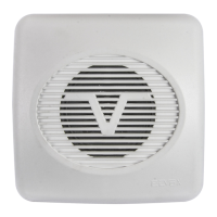
Diagram illustrating the connection of an external chime for call repeating.

Diagram Symbols Reference

Explains the meaning of various symbols used throughout the installation diagrams.

Software Updates and Function Notes

Key Software Improvements

Summarizes significant software improvements and new features applied to the system.

Functionality Notes (F1, F2, Lock, F6-F8)

Provides detailed notes and explanations for specific functions like F1, F2, door lock, and F6-F8.

Compliance and User Information

Installation Rules and Conformity

Outlines installation guidelines, EMC directives, and product conformity standards.

WEEE Directive Information

Information for users regarding the disposal of electrical equipment according to WEEE regulations.

Overview

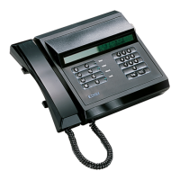
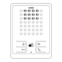
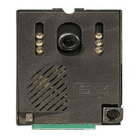
The Vimar 945B/945B/I Porter's Switchboard is a desktop unit featuring a black thermoplastic housing, designed for managing and controlling various functions within a building complex. It supports up to 99,999,999 users and is equipped with a 20-key keypad for entering user numbers, making calls, activating intercom or conference functions (excluding the building complex), releasing the door lock, and for F1-F2 functions. It also allows for the cancellation of operations in progress. The switchboard can store up to 30 different calls, which can be scrolled through using the memory scroll button. It includes a watch with time and date display and two wake-up functions. An optional printer can be managed with the 945B/I model, which includes a printer interface.

Technical Specifications:

  • User Capacity: Up to 99,999,999 users.
  • Keypad: 20 keys for numerical input and function activation.
  • Call Storage: Up to 30 different calls in a circular buffer.
  • Display: 40x2 LCD, divided into 5 zones for clear data distinction.
  • Power Backup: Internal watch backed up by a capacitor (approx. 4 days dwell time during mains failure).
  • Printer Interface: Optional for 945B/I model, supports various parallel circuit board printers.
  • Programming Access Code: Default 123.
  • Keypad Disable Code: Default 27.
  • Number of Digits: Selectable 4 or 8 digits (default 4).
  • Language: 0 = Italian, 1 = English (default 0).
  • Entrance Panel Prefix: 0-99 (default 99).
  • Lock Enable: 0 = NO, 1 = YES (default 1).
  • Camera Enable: 0 = NO, 1 = YES (default 1).
  • Sound Enable: 0 = Disable all chimes, 1 = Enables internal call chime, 2 = Enables external and internal call chime (default 2).
  • Ring Time Enable: 0 = NO, 1 = YES (default 1).
  • Function Display Enable: 0 = NO, 1 = YES (default 1).
  • Switchboard Dialling Code 1: 0-99 (default 0).
  • Call Repeat Number: 1-255 (default 3).
  • Conversation Time: 1-255 (value x 10 seconds, default 12 = 120 seconds).
  • Ring Duration: 1-255 (value x 1 second, default 1).
  • Answer Time: 1-255 (value x 1 second, default 30).
  • F1/F2 Time: 1-255 (value x 1 second, default 1).
  • Lock Time: 2-255 (value x 1 second, default 1).
  • Printer Set: 0-255 (default 1).
  • External Call Transit Enable: 0 = NO, 1 = YES (default 0).

Function Description:

Display Management (40x2):

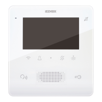
The display is organized into five zones:

  • Upper Line (Left): Outgoing messages and specific information signals.
  • Upper Line (Centre): Number to be dialled (8 digits) or corresponding message.
  • Upper Line (Right): Current time.
  • Lower Line (Left): Incoming messages (from internal units or external lines) and respective numbers.
  • Lower Line (Right): Icons indicating various states/functions.

Icon Description:

  • (Box with arrow, followed by a number): Indicates calls or commands in memory (e.g., "5" for 5 queued calls).
  • (Telephone handset): Handset is lifted.
  • (Arrow toward wire at left): Operator intromission in conversation line.
  • (Key): Lock release or function activation in progress.
  • (Bell in movement): Call in progress (ringing). Changes to "A" (Wait for answer) then "C" (Conversation in progress) with hooked handset.
  • (Telephone in movement): Connection with telephone line.
  • (Lock): Locked keypad by external key.
  • (Int) (Ext): Switchboard state (Internal or External mode).
  • (Exclusion of sound): Sound excluded (R+3).

Quick Guide:

  • Parameter Programming:
    • Display date/time/wake-up: R+2 (or R+"8->8").
    • Enter code for keypad lock: R+1.
    • Activate accessory functions: KEY.
    • Program events to store: R+MEM.
    • Program events to print: Press MEM again.
    • Set wake-up service 1/2 time: Press MEM again.
    • Set time/date: Press MEM again.
  • Exclusion/Reactivation of Audio: R+3.

Stored Calls:

The switchboard can store up to 30 "events" (calls from interphones, function activations, door lock releases, calls from switchboard). These events are stored in a circular queue on the watch-backed RAM, ensuring no data loss during mains failure. Events can be sent to a printer (with 945B/I). A flashing icon and sound signal new stored events.

Internal Watch with Date, Time, and 2 Wake-Up Services:

Displays current date and time, backed up by a capacitor. Two wake-up services can be programmed.

Audio Events:

Different sounds for various events (riser call, external line call, wake-up service). Melodies can be programmed via software and PC interface.

"Software" Lock Key:

The keypad can be locked using a password (1-32000), set in technical parameters ("CHIAVE BLOC SW."). Activate/deactivate with R+1.

Simplified Management of "Internal-External" Mode Push-Button:

The I/E button switches between internal and external modes. A display symbol ("I" or "E") and the "EXTERNAL" LED indicate the current mode. The state is stored in EEPROM.

Managing the Printer:

Connects via an optional internal interface. Supports various parallel printers. Software manages different models. Selectable data for reception or transmission.

Circuit Board Re-Programming "In-Circuit":

The circuit board can be reprogrammed via a connector, useful for special versions.

Possible Connection Toward a PC:

Allows downloading events, managing configuration parameters, names, and functions. Also for modifying musical melodies, direct event recording, and partial self-diagnosis.

Operation:

Displaying Time, Date, Wake-Up Time-Table:

Time is always on the top right. Other data (date, wake-up times) displayed with R+2.

Activation of Lock Release, F1, F2, and Accessory Functions F6, F7, F8:

Press "KEY" to access a menu (0=LOCK; 1=F1; 2=F2; 6=F6; 7=F7; 8=F8). Numerical input activates the corresponding command. "KEY" icon activates during activation time.

Switchboard Lock by Means of a Software Key:

Activates/deactivates keypad lock with R+1 and password (default 27). Display shows "!BLOCCO CHIAVE!" when locked.

Queue of Stored Calls:

Memory stores up to 30 requests (calls, F1/F2, lock release) with reception time. An icon signals events. Scroll with "MEM". Transfer numbers to call display with "8->8". Clear memory by pressing "MEM" for 3 seconds.

Programming Menu:

Access with R+MEM. Functions include:

  1. Commands to be Stored ("COM. TO MEMO"): Selects commands (CH, F1, F2, LOCK, F7, F8, CNT) to be stored in the circular buffer. Sum of values (e.g., 7 for CH, F1, F2).
  2. Commands to Print ("COM. TO PRINT"): Selects commands (CH, F1, F2, LOCK, CENT) to be sent to the printer. Sum of values. Set to 0 if no printer is connected.
  3. Wake Up Service N. 1 ("RING 1 (hhmm)"): Programs daily wake-up time (hhmm). Dial 9999 to disable.
  4. Wake Up Service N. 2 ("RING 2 (hhmm)"): Second wake-up service.
  5. Time ("TIME (hhmm)"): Sets current time (hhmm).
  6. Date ("DATE gg mm aa"): Sets current date (gg mm aa).

Printing Activation:

Requires a 945B/I interface and a parallel printer. Access programming menu (R+MEM), select "PROGRAMMING OF COMMANDS TO BE SENT FOR PRINTING". Set "Printer Setup" parameter (default 0) to adapt to printer type.

  • 0 (default): Line by line with CR (for matrix printers).
  • 16: Line by line with CR+LF (for some ink-jet printers).
  • 16+3 (or 16+1...7): CR+LF with paper expulsion every X lines (X*10).
  • 3 (or 1...7): CR with paper expulsion every X lines (X*10). To force paper expulsion, press R+C.

Melody Management:

5 melodies associated with events. Time dwell is variable. Listen/shorten melodies with R+II. Download new melodies via serial interface (software) or copy from another 24C02 memory with R+INT/EXT.

Meaning of Main Technical Characters:

  • Numero Targa (Entrance panel number): Digibus number for switchboard.
  • Numero Digit (Digit number): Selects 4 or 8 digits.
  • Chiave Blocco Software (Software lock key): Keypad lock password.
  • Num.Rip.Chiamate (Call rip. number): Number of call sound repetitions.
  • Abil.Suoni (Sound enable): Activates melodies (0=never, 1=Int mode, 2=Int/Ext mode).
  • Set Stampante (Printer Setup): Selects printing modes.

Call Operations:

  • External Operation (EXTERNAL lamp "on"):
    • Call from entrance panel to user: Direct call, switchboard notified by LINE lamp and number. Interrupt with R (Internal mode), enter conversation with 8<>8 then MEM. Release door lock with LOCK.
    • Direct call to switchboard from main entrance panel: Uses "SYSTEM NUMBER". Switchboard activates call signal, displays "CALL YOU FROM EXT.", connects. Open door with LOCK.
    • Porter call: Calls to switchboard recorded and displayed. Acoustic signal disabled. Manage calls in Internal mode.
  • Internal Operation (EXTERNAL lamp "off"):
    • Call from switchboard to internal unit: Enter user number, press BELL. Switchboard connects, activates video camera. Disconnects if no answer or after conversation time.
    • Call from main entrance panel to switchboard: Switchboard intercepts calls, switches to entrance panel, activates monitor. Displays called number. Release door lock. Communicate with entrance panel using MEM.
    • Call from entrance panel with switchboard in internal mode: Switchboard intercepts, routes to internal unit. Operator calls internal unit with 8<>8 then BELL. Transfers line to panel with MEM. "Hold" signal transmitted to entrance panel.
    • Call from user to switchboard: Users call with door lock release button. Switchboard displays number. Communicate with 8<>8 then BELL. Cancel with R. Scroll multiple calls with MEM.
    • Intercommunication between internal units: One unit calls switchboard. Operator calls both units with BELL, then connects with MEM.
    • Conference between internal units: Operator calls first unit with BELL, then connects other units one by one with MEM. Switchboard remains connected.
    • Conversation with telephone line: Connects internal unit to external telephone line.
      • Incoming call: Reply with telephone, transfer to internal unit with BELL then MEM.
      • Outgoing call: Internal unit calls external user with telephone, then calls internal unit with code and BELL then MEM.
    • Notification: Switchboard enters ongoing conversation (intercom, conference, telephone, entrance panel). Acoustic warning signal. Exclude with R.

Adjustments and Description of Terminals:

  • Trimmers:
    • P1: Digital signal current generator (25 mA).
    • P2: Switchboard acoustic call signal volume.
    • P3: LCD contrast.
  • Terminals:
    • (H): Not used (945B).
    • (CH): Call signal activation.
    • (S): Electric door lock activation.
    • (F1), (F2): Auxiliary function 1/2 activation.
    • (3C): Acoustic call.
    • (4), (9): Supply voltage negative.
    • (5), (10): Supply voltage +13.5 Vdc.
    • (R+), (R-): Additional bell connection.
    • (I+), (I): Monitor deactivation.
    • (T): Video camera deactivation.
    • (1), (3): Digital/phonic signal to interphone/monitor cable riser.
    • (6), (8): Digital/phonic signal to main entrance panel.
    • (aa e bb), (a e b): Telephone connection/external telephone line.

Minimum Conductor Section (mm²):

Provides a table for recommended conductor sections based on distance (up to 200m) for 4-5, + - and lock, others, and video (coaxial cable 75 Ohm). Includes a conversion table for sections, diameters, and resistances for 100m standard conductors.

Interphone Riser Diagrams:

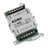
Includes diagrams for interphone risers with and without floor distributors (Art. 949B), and monitor cable risers with internal digital signal decoding. These diagrams are essential for installation.

Main Improvements/Software Modifications:

  • External Repetition of Call Ringtones: F2 terminal can be used for ringtone repetition (if F2 parameter is 0).
  • Transit of Calls from External Entrance Panel: "Ab.Transi.Esterno" parameter (1=upline transit, 0=disabled).
  • Manual Activation of Audio Line to Cable Riser: Conference key for 3 seconds activates audio for voice communication.
  • Improvements: Cable riser disengaged immediately after handset replacement if interphone doesn't answer.
  • VIEW Function: Added to Digibus commands for programming and alarm.
  • Functions F1, F2, Door Lock, F6, F7, F8: Details how these functions activate specific terminals and how commands are re-sent downline.
  • Door Lock Release: Activates local lock terminal "S". Command sent downline only if communicating with external entrance panel.
  • Functions F6, F7, F8: Commands repeated to external digital signal. Useful for activating external devices (170/D or 170/F).

Vimar ELVOX 945B Specifications

General IconGeneral
BrandVimar
ModelELVOX 945B
CategoryIntercom System
LanguageEnglish

Related product manuals