12
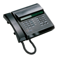
ADJUSTMENTS AND DESCRIPTION OF TERMINALS
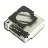
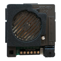
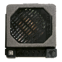
Adjustment trimmers
The following trimmers are fitted on the back of the switchboard:
P1- Adjusts the digital signal current generator (d.c. value 25 mA must not be changed unless otherwise specified).
P2- Adjusts the volume of the switchboard acoustic call signal.
P3- LCD contrast.
Switchboard terminals.
H) Not used by switchboard Art. 945B.
CH) Terminal controlling call signal activation.
S) Terminal controlling electric door lock activation.
F1) Terminal controlling activation of auxiliary function 1.
F2) Terminal controlling activation of auxiliary function 2.
3C) Acoustic call terminal.
4) Supply voltage negative terminal.
5) Supply voltage terminal + 13.5 Vdc.
R+ e R-) Additional bell connection terminals.
+I) Terminal controlling monitor deactivation.
I) Terminal controlling switchboard monitor deactivation.
T) Terminal controlling switchboard video camera deactivation.
1) Terminal controlling digital signal to interphone/monitor cable riser.
3) Terminal controlling phonic signal to interphone/monitor cable riser.
6) Terminal controlling digital signal to main entrance panel.
8) Terminal controlling phonic signal to main entrance panel.
9) Supply voltage negative terminal.
10) Supply voltage terminal + 13.5 Vdc.
aa e bb) Telephone connection terminals.
a e b) External telephone line connection terminals.