20
BASIC DIAGRAM VERSIONS
VERSION 1A
Supplementary function F1-F2 connections
in installations with interphones without
internal decoding.
An additional entryphone controlled function (F1-F2)
can be activated by connecting relay Art. 0170/001
as per diagram.
N.B. Entry phones Art. 8877 - 6201 can control one
additional function only. To make sure of both the
additional functions, install entry phones type 6201
with additional push-buttons Art. 0002/903 and con-
nect another relay to the R2 - 4 terminals of the
power supply. One or more extra alarm push-buttons
can also be fitted directly onto the distributor (P1-P2).
A
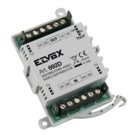
A- Digital distributor
Art. 949B
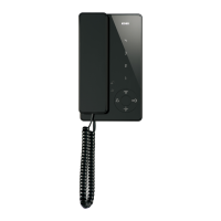
Phone
Art. 8877
Mains
Relay
Art. 0170/001
P1-
Push-button for “F1” function
P2-
Push-button for “F2” function
Relay
Art. 0170/001
X- “F1” additional function
Y- “F2” additional function
INTERPHONE CABLE RISER
VERSION 1B
Supplementary function F1-F2 connections in
installations with interphones with internal deco-
ding.
An additional entryphones controlled function (F1-F2) can be
activated by connecting two relays Art. 0170/001 as per dia-
gram.
NOTE: In interphone type 6204 add one Art. 6C59, while in
interphone type 887B, 887B/1 only function F1 is possible.
Mains
Power supply
Art. 6941
INTERPHONE CABLE RISER
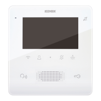
Phone
Art. 6204 + Art. 6C59
Phone
Art. 887B
Art. 887B/1
Relay
Art. 0170/001
Relay
Art. 0170/001
X- “F1” additional function
Y- “F2” additional function
Power supply
Art. 6941
Phone
Art. 6201
Phone
Art. 8877
Phone
Art. 6204 + Art. 6C59