EasyManua.ls Logo

Vimar ELVOX 7558/E User Manual

Vimar ELVOX 7558/E
44 pages
To Next Page IconTo Next Page
Page #1 background imageLoading...
Page #1 background image
Manuale di installazione e utilizzo - Installation and operation manual
Manuel d'installation et d’utilisation - Installations- und Bedienungsanleitung
Manual de instalación y uso - Manual de instalação e utilização

  
7558/E - 7558/E2
Kit videocitofonico Due Fili Plus monofamiliare/bifamiliare
Due Fili Plus one-family/two-family video entryphone kit
Kit visiophonique Due Fili Plus pour un ou deux logements
Set Videohaustelefon Due Fili Plus für Ein-/Zweifamilienhäuser
Kit de videoportero Due Fili Plus uni/bifamiliar
Kit de videoporteiro Due Fili Plus monofamiliar/bifamiliar

/  Due Fili Plus    
PRI
1 2
B1 B2
6922.1
POWER SUPPLY UNIT
PRI: 110-240V~ 1-0,6A 50/60Hz
1/2 B1/B2: 28V 1A CONT+0,6A INT
ESV160250
PRI
1 2
B1 B2
6922.1
POWER SUPPLY UNIT
PRI: 110-240V~ 1-0,6A 50/60Hz
1/2 B1/B2: 28V 1A CONT+0,6A INT
ESV160250

Other manuals for Vimar ELVOX 7558/E

Question and Answer IconNeed help?

Do you have a question about the Vimar ELVOX 7558/E and is the answer not in the manual?

Vimar ELVOX 7558/E Specifications

General IconGeneral
TypeVideo Intercom
Resolution800 x 480 pixels
CameraYes
Night VisionYes
MaterialPlastic
DisplayTFT LCD
InstallationWall-mounted

Summary

Package Contents

Key Functions and Button Operation

Touch Button Functions

Installation Guidelines

Step-by-Step Installation

Details the sequential steps for installing the device, including wiring.

Plate Installation

Flush Mounting Plate Installation

Instructions for installing the plate in a recessed wall mount.

Terminal Connections

Connection Terminal Block Details

Identifies terminals for bus, landing call, and ground connections.

Connection Diagram Labels

Explains the function of each terminal connection point.

External Panel Installation

Flush Mounted Plate Installation

Surface Mounted Plate Installation

Terminal Block and Function Descriptions

Terminal Identification (M, CA)

Defines the function of terminals M (Ground) and CA (Door lock/sensor).

Terminal Identification (B1, B2, S-, S+)

Defines the function of terminals B1, B2 (BUS) and S-, S+ (Lock).

Dip-Switch Configuration Options

Power Supply Unit 6922.1

Technical Characteristics of Power Supply

Details electrical specifications, power consumption, and operating temperature.

Installation Rules for Power Supply

Provides safety and installation guidelines for the power supply unit.

Wiring Diagrams

One-Family System Wiring

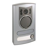
Diagram for a single-family system with one entrance panel.

System Component Identification

Two-Family System Wiring Diagram

General Installation Rules and Safety

Installation Compliance and Precautions

Details installation requirements, safety measures, and user warnings.
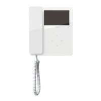
Related product manuals