17
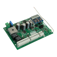
SW24.W
LRNT
LRNA
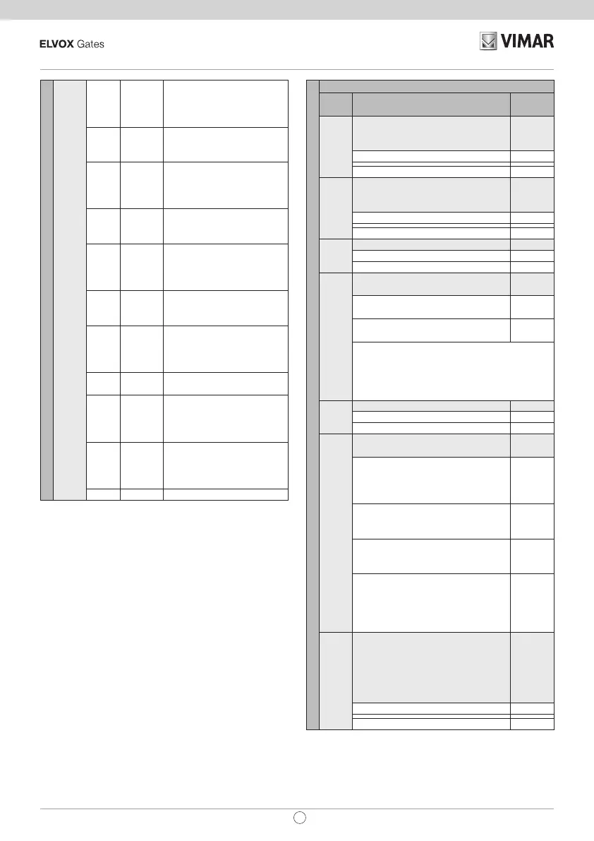
PP OP 2 Start opening motor 2
When button pressed:
slowdown start position on
opening setting.
PP OP 2 When button pressed end
of travel position setting or
continuation to the stop.
PP CL 2 Start closing motor 2 When
button pressed: slowdown
start position on closing
setting.
- CL 2 Continuation of motor 2
closing at slowdown speed
up to stop.
PP CL 1 Start closing motor 1 When
button pressed: slowdown
start position on closing
setting.
- CL 1 Continuation of motor 1
closing at slowdown speed
up to stop.
OPED Start pedestrian opening.
When button pressed:
pedestrian opening posi-
tion setting
- CPED Leaf closing from pedes-
trian opening position
PP DLOP Start opening. When
the oset time setting in
opening button is pressed,
motor 2 starts.
PP DLCL Start closing. When the o-
set time setting in closing
button is pressed, motor
1 starts.
- END End of procedure
Self-calibration:
If the gate travel parameter is changed, there is no need
for the installer to run new calibrations, however, when
changing the travel parameters, the control panel needs
to learn the current curve again, thus disabling the obsta-
cle detection only during the self-calibration manoeuvre.
Self-calibration is appropriately signalled:
- on the control panel display by the code AT
- by the light ashing at twice the normal frequency
The events generating self-calibration are:
- change in parameters: T24, T25, T26, T27, T28, T29,
T30, T31, T32, T33, T34, T35, T40, T41
- loading of settings from a MEM.W memory card
- reset/import of settings from the Wi-Gate app
TRV
Gate travel parameters
Sub
menu
Description Values
(default)
T1
Motor 1 force (%).
Sets the value of the force given to
the motor to push the leaf
(50)
Minimum force 1
Maximum force 100
T2
Motor 2 force (%).
Sets the value of the force given to
the motor to push the leaf
(50)
Minimum force 1
Maximum force 100
T3
First leaf to move (M1)
Motor 1 M1
Motor 2 M2
T4
Direction.
Sets the motor direction
(1)
Standard (a linear motor closes the
gate with pistons extended)
1
Inverse (a linear motor closes the
gate with pistons retracted)
2
Note:
Inverts both motors. If only one motor has
an incorrect direction, invert the power
supply wires on the motor with the incorrect
direction.
T6
Number of motors (2)
Single-leaf gate 1
2 leaf gate 2
T7
Choice of intervention method
for obstacle detection
(1)
Overcurrent or leaf stopped:
the obstacle is detected when the
current threshold or the encoder
slowdown threshold is exceeded
1
Leaf stopped: the obstacle is
detected only when the leaf slows
down excessively
2
Overcurrent: the obstacle is de-
tected when the current threshold
is exceeded
3
Overcurrent and leaf stopped:
the obstacle is detected when the
current threshold and the encoder
slowdown threshold are exceeded
at the same time
4
T10
Obstacle detection time motor 1
Time after which the current
threshold or the encoder threshold
trigger the obstacle detection for
motor 1 (adjustable at intervals of
100 ms)
(20)
100 ms (minimum time)
10
600 ms (maximum time) 60
EN
 Loading...