26
SW24.W
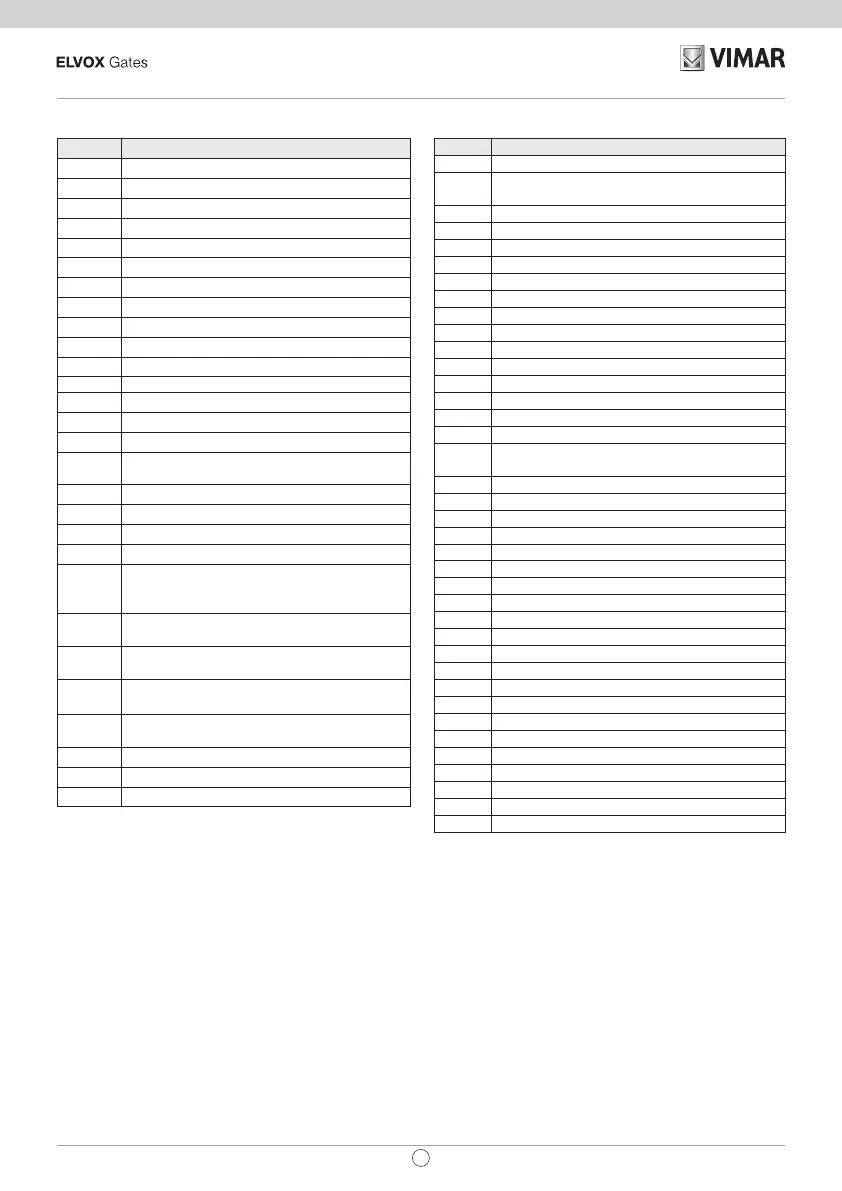
List of signalling on the display
Signal Description
C1 Contact closed on command C1 input
C2 Contact closed on command C2 input
C3 Contact closed on command C3 input
C4 Contact closed on command C4 input
S1 Contact open on safety device S1 input
S2 Contact open on safety device S2 input
S3 Contact open on safety device S3 input
S4 Contact open on safety device S4 input
FO1 Opening limit switch position reached motor 1
FC1 Closing limit switch position reached motor 1
FO2 Opening limit switch position reached motor 2
FC2 Closing limit switch position reached motor 2
OB1 Obstacle detected motor 1
OB2 Obstacle detected motor 2
AF1 Motor in stop approach force reduction interval
AF2
Motor 2 in stop approach force reduction in-
terval
MSO1 Mechanical stop reached in opening motor 1
MSC1 Mechanical stop reached in closing motor 1
MSO2 Mechanical stop reached in opening motor 2
MSC2 Mechanical stop reached in closing motor 2
BATT
Operation with battery. When this message is
displayed it is followed by an indication of the
battery operating voltage, e.g. 24.5V
BT-
Battery almost at (indication shown only
when the gate is stopped)
BT--
Battery totally at (indication shown only when
the gate is stopped)
RX
Radio command received from saved remote
control or from App
NX
Radio command received from unsaved re-
mote control button
RD Rolling/xed code decoding o
OAB Gate left open
AT Gate in self-calibration
List of alarms
Alarm Description
XXXX Reset card
MNP
Manoeuvre interval since last maintenance
reached alarm
F0 Error motor not selected
F1 Motor 1 cables inverted error
F2 Motor 2 cables inverted error
F3 Reversed limit switch error
F4 Both open limit switch alarm
F5 Opening limit switch malfunction error motor 1
F6 Closing limit switch malfunction error motor 1
F7 Opening limit switch malfunction error motor 2
F8 Closing limit switch malfunction error motor 2
F9 Communication error with expansion card
F10 Error alarm motor 1 not connected
F11 Error alarm motor 2 not connected
F12 Motor 1 encoder error alarm
F13 Motor 2 encoder error alarm
F14
Microswitch undervoltage (check power supply
and outputs)
F15 Safety test 1 failed
F16 Safety test 2 failed
F17 Safety test 3 failed
F18 Safety test 4 failed
F19 Motor 1 manoeuvre length/timeout alarm
F20 Motor 2 manoeuvre length/timeout alarm
F21 Motor 1 mosfet short alarm
F22 Motor 2 mosfet short alarm
F23 Blocked rotor alarm motor 1
F24 Blocked rotor alarm motor 2
F25 Overlapping leaf in closing alarm
F26 5th obstacle in closing alarm
F27 Overcurrent alarm motor 1
F28 Overcurrent alarm motor 2
F29 Radio memory full alarm
F30 Faulty radio memory alarm
F31 Short ashing alarm
F32 Gate open light short alarm
F33 No memory card alarm
F34 FW checksum alarm
F36 Board temperature alarm
Updating Firmware:
The control panel is equipped with a USB port that is
used to update the control panel Firmware or the Wi-Fi
EMC.W communication module Firmware
Caution:
If the rmware updating procedure is not carried out prop-
erly it may damage the control panel or the Wi-Fi com-
munication module, make sure not to interrupt the mains
power supply during the update.
To perform the Firmware Update, consult the instructions
provided with the Firmware
EN
 Loading...