7602026
25
11) FINAL TESTING
Supply power to the system and perform the
following functional checks:
- Load test:
- Load the lift with 1.1 times the rated load stated on
the nameplate.
- Send the lift up and down several times, checking its
stability on the rail.
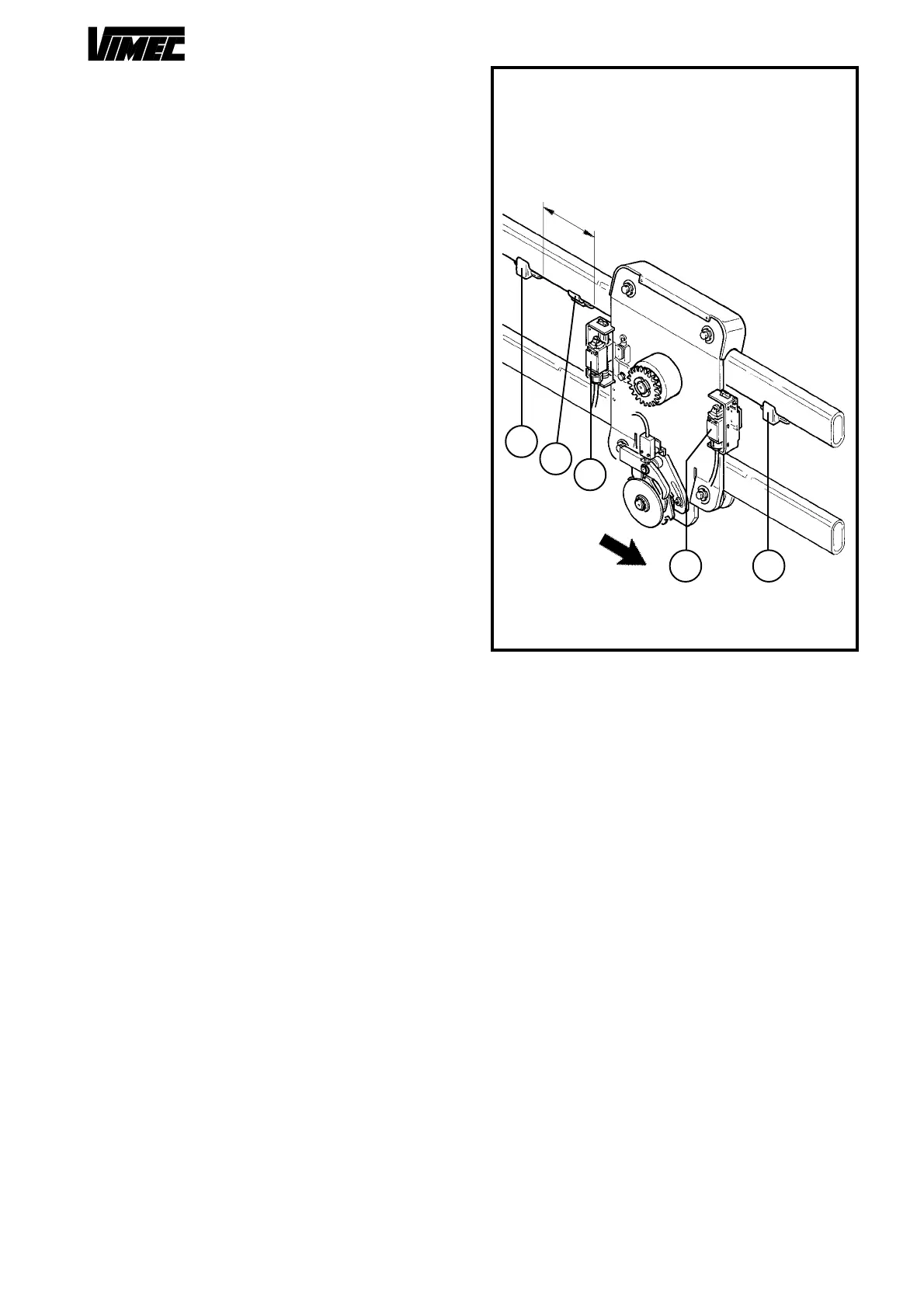
- Drive the machine to the upper level and place the
platform as to let the unloading of the bodywork and
assemble the cam on the guide (Fig. 33/a), so that the
rise limitstop micro is pressed on (Fig. 33/b).
- Drive the machine to the lower level and place the
platform as to let the unloading of the bodywork and
assemble the cam on the guide (Fig. 33/c),so that the
descent limitstop micro operates (Fig. 33/d).
- Repeat the operation to check the operating of the
limit stop and extra stroke micro, making the machine
rise and descent.
-Lock the cams with the indicated cylindrical pin Ø4x30.
- Place the third cam (mechanical extra stroke) with
the indicated cylindrical pin Ø4x30, on the guide decent
side paying attention to assemble it rotated 180° (Fig.
33/e).
- Preliminary checks
Perform the checks described in point 6.1 on page 8 of
the Use and Maintenance Manual.
- Safety gear test
Test the safety gear as described in Section 9, point
d.
(This test must be carried out with no load on the lift).
- Check on fixing of the rail
- Check that the rail is positioned in accordance with
the dimensions stated in the installation drawing (or
system layout) supplied with the lift.
- Check that all the fixing screws of the connections to
the mounts or any expansion plugs are stable and firmly
tightened.
FIG.33
SN CARRIAGE CONFIGURATION
FRONT VIEW
M
A
C
H
I
N
E
A
D
V
A
N
C
E
R
I
S
E
S
I
D
E
D
E
S
C
E
N
T
S
I
D
E
a
e
~
1
3
0
c
d
a
 Loading...


