7.11 REPLACING THE COMPRESSOR, COMPRESSOR PTC STARTER AND OVERLOAD
PROTECTOR
NOTE: Before replacing any component of the refrigeration system, make sure to read the
instructions “Service Precautions for R600A System” or “Service Precautions for R134a System”.
All replacement compressors are charged with the correct amount of oil and a holding charge of
dry nitrogen.
The holding charge is your assurance that the compressor is dry and ready to install. If you
receive a replacement compressor that shows no evidence of holding charge when you center
the lines or remove the plugs, return it.
1. Disconnect the unit from the source.
2. Locate defective compressor and evacuate the sealed system.
3. Clean and cut the refrigerant lines as close as possible to the compressor stubs, leaving
enough length to install the replacement compressor.
4. Disconnect lead wires from compressor terminals.
5. Remove the retaining clips from the compressor mounts. Remove defective compressor
from cabinet and install rubber grommets on replacement compressor.
6. Clean the compressor stubs with an abrasive cloth. Do not open the compressor stubs.
7. Install the replacement compressor using the mounting clips previously removed.
8. Connect the compressor leads.
9. Solder a short piece of tubing to the process tube (approximately 150mm / 6 inches long).
Connect the refrigerant tubing to the compressor stubs
10. Evacuate, recharge and leak test the system.
11. Test/run the unit to check operation.
7.12 REPLACING THE FILTER DRIER
NOTE: A new filter drier must be installed each time any component of the refrigeration system
opened or replaced.
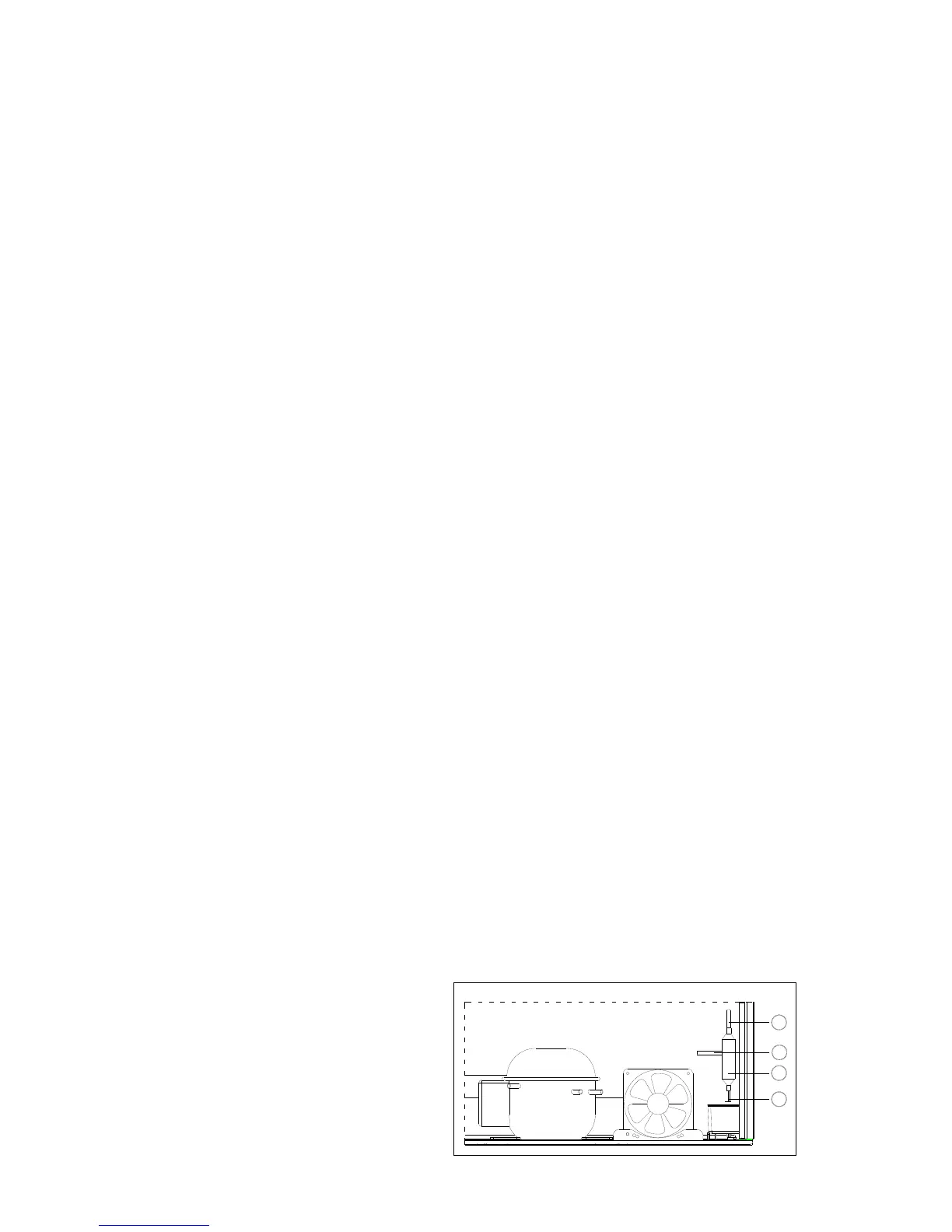
1. Carefully pull the old filter drier
○
2 and tubing out of the compressor room.
2. Use steel wool or fine emery paper to clean the capillary tube
○
1 3 inches (75mm) from the
original joint. Also, clean the input tubing
○
4 (the condenser outlet tube) to the filter drier
of 3 inches from the original joint.
3. Use a knife or file to score the capillary tube and the input tubing to the old filter drier 1 inch
(25mm) from the original joints. Then break the connections.
4. Use steel wool or fine emery paper to clean both ends of the new filter drier.
5. Make an offset 1/2" (12mm) from the end of the capillary tube to prevent it from penetrating
too far into the drier.
6. Connect the capillary tube to the replacement filter drier.
7. Connect hot pipe inlet tube to the replacement filter drier
8. Solder the new filter drier using silver solder with the proper flux at the hot pipe to filter drier
joint. Use silfos at the drier to capillary tube joint.
2
3
4
1
 Loading...