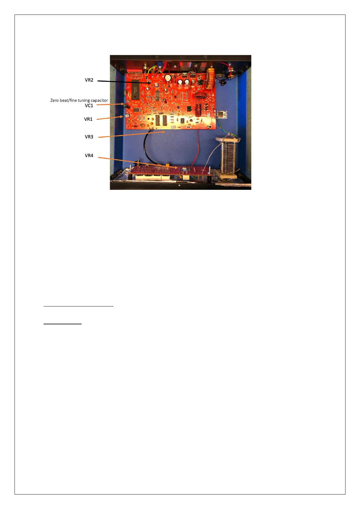
The Variable Inductor is located to the top-right of the circuit board. (the round coil)
Resetting the Frequency display
The Programmed Chip can get swamped with RF and makes it display incorrectly. (this is
very uncommon but has been observed)
A micro switch has been fitted to the display board to allow the display to be reset. Press
the switch once to enter setup. Press through the stages, so that you select ‘No PS’ (does
not enter ‘sleep mode’), Zero (offset) press and hold until it flashes to set this and press to
hold for exit to save setup.
Technical Specifications
20 Watt Unit
Size - 220mm wide, 240mm depth, 90mm high
Weight. - 1.45Kg
Power requirement - DC 24 -28 V @ 2.5A max
Audio input – RCA Phono sockets, left and right audio between 75mV and 775mV RMS
Audio Bandwidth (+ -3dB) - 80Hz to 6KHz
Modulation level – up to 100%
RF Output level – Average 20 Watts (dependant on Frequency and Aerial Match)
RF Output Capacitor – 400pF variable 750V rated
RF connection – screw terminal for signal and earth connection
Display -
Signal level – 10 segment Bar-Graph multi-colour LED
Frequency – 4 7-segment LED display
Ventilation – passive convection, heatsink to rear.
 Loading...