EasyManua.ls Logo

Vintronics AM PLL - User Manual

Vintronics AM PLL
9 pages
Print Icon
To Next Page IconTo Next Page
Loading...
AM PLL High Power Medium-Wave Transmitter
A High-Power version of AM Transmitter, operating between 620KHz and 1024KHz in the
Medium Waveband (AM Band) and are designed to be reliable and stable units.
They can deliver up to 20 watts of RMS power into a short length aerial. This equates to 80
watts peak power cleanly driven up to 100% modulation.
This transmitter has been designed to operate into a fairly short ‘long-wire’ aerial, minimum
length approximately 12 metres and up to 25 metres. Anything shorter than this is very
inefficient and may make critical components overheat. Obviously the longer the better.
Each Transmitter circuit design employs a Colpitts FET oscillator in a Phase-locked loop
circuit for accuracy and ease of frequency selection. It is also very stable and therefore does
not drift off frequency. The Phase Lock circuit provides selection in 1KHz steps, so that the
unit can be used in either Europe, which has 9KHz spacing between channels, or in the USA
and other parts of the World where 10kHz is used between channels. A rugged Power
MOSFET is also used on the RF output stage, which drives the output toroid and variable
tuning capacitor. High voltage rated components are used in the output section.
Audio modulation is series-derived using Power Transistors. It is driven by an audio level
control chip which allows the transmitter to always achieve maximum modulation,
whatever the audio source and nominal level is, within reason. (CD player, mixer, PC etc)
Housed in a Steel box with ABS front and rear panels. Ventilation holes to improve air flow
for component cooling. A fan is used on higher output models where necessary.
Question and Answer IconNeed help?

Do you have a question about the Vintronics AM PLL and is the answer not in the manual?

Summary

Power Supply Safety

Power Supply Warning

Important safety note regarding the use of correct power units to avoid damage.

Setup and Operation

Setup Instructions

Step-by-step guide for connecting and preparing the transmitter for use.

Frequency Setting

Procedure for setting the operating frequency using DIP switches on the rear panel.

Aerial Matching

Importance of matching the aerial for optimal RF signal and transistor protection.

Advanced Setup and Troubleshooting

Guidance on aerial matching, using links, and improving range with longer aerials.

Adjustment and Alignment

PLL Alignment

Steps to align the Phase-Locked Loop for frequency accuracy.

RF Drive Adjustment

Adjusting the signal drive to the output FET for maximum output.

Audio Level Adjustment

Setting audio level for maximum modulation without carrier distortion.

Hum Cancel Adjustment

Adjusting VR1 to introduce a low-level signal for hum cancellation.

RF Level Monitor

Understanding the bargraph display as a carrier and modulation indicator.

Aerial Matching Details

Using selector links on toroids for optimal aerial matching at higher frequencies.

Technical Information

Resetting Frequency Display

Procedure for resetting the programmed chip if the display shows errors.

Technical Specifications

Key specifications including size, weight, power, and connectivity.

Overview

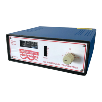
The device described is an AM PLL High Power Medium-Wave Transmitter, designed for reliable and stable operation within the Medium Waveband (AM Band), specifically between 620KHz and 1024KHz.

Function Description

This transmitter is a high-power unit capable of delivering up to 20 watts of RMS power into a short length aerial, which translates to 80 watts of peak power with clean 100% modulation. Its primary function is to broadcast audio signals over the AM band. The core of its design incorporates a Colpitts FET oscillator within a Phase-locked loop (PLL) circuit, ensuring accuracy and ease of frequency selection, as well as preventing frequency drift. The PLL circuit allows for frequency selection in 1KHz steps, making it suitable for use in regions with 9KHz channel spacing (like Europe) or 10KHz spacing (like the USA and other parts of the world).

The RF output stage utilizes a rugged Power MOSFET, driving an output toroid and a variable tuning capacitor. High-voltage rated components are employed in the output section to handle the power requirements. Audio modulation is achieved through a series-derived method using Power Transistors, driven by an audio level control chip. This chip ensures maximum modulation regardless of the audio source's nominal level (e.g., CD player, mixer, PC), within reasonable limits.

The transmitter is housed in a steel box with ABS front and rear panels, featuring ventilation holes to enhance airflow for component cooling. Higher output models may also include a fan for additional cooling.

Important Technical Specifications

20 Watt Unit:

  • Size: 220mm wide, 240mm depth, 90mm high
  • Weight: 1.45Kg
  • Power Requirement: DC 24-28 V @ 2.5A max (from an external plug-top power unit)
  • Audio Input: RCA Phono sockets, left and right audio between 75mV and 775mV RMS
  • Audio Bandwidth (+-3dB): 80Hz to 6KHz
  • Modulation Level: Up to 100%
  • RF Output Level: Average 20 Watts (dependent on Frequency and Aerial Match)
  • RF Output Capacitor: 400pF variable 750V rated
  • RF Connection: Screw terminal for signal and earth connection
  • Display:
    • Signal level: 10 segment Bar-Graph multi-colour LED
    • Frequency: 4 7-segment LED display
  • Ventilation: Passive convection, heatsink to rear (fan on higher output models where necessary)

Usage Features

Setup:

  1. Insert the stripped end of the aerial wire into the Aerial terminal and secure it.
  2. Remove the top cover to access the variable inductor.
  3. Adjust the operating frequency using DIP switches located on the rear panel according to the desired settings (refer to the binary switch positions table for frequency selection).
  4. Connect phono audio cables (L and R) from the audio source (e.g., CD player, mixer, PC) to the transmitter.
  5. Connect the supplied power supply to the DC socket and turn on the unit.
  6. Adjust the aerial tune knob and the internal variable inductor to achieve maximum power on the output power display.
  7. Switch off the unit and replace the top cover.

Aerial Requirements: The transmitter is designed to operate with a "long-wire" aerial, with a minimum length of approximately 12 meters and up to 25 meters. Longer aerials are generally more efficient. A recommended arrangement involves a single long wire of approximately 18 meters, using insulators and suspended from a rooftop or tree. The use of a good Earth connection (e.g., a copper stake in the ground) is also recommended for improved signal efficiency and distance.

Frequency Selection: Frequency is set using a bank of 10 DIP switches on the rear of the transmitter. Each switch corresponds to a binary digit (up for '1', down for '0'). A frequency table is provided to convert desired frequencies (e.g., 1017KHz) into their corresponding binary switch settings.

Power Supply: Only the specific external plug-top power unit supplied with the transmitter should be used. Using an incorrect power voltage can damage voltage-sensitive internal components.

Maintenance Features

Adjustment and Alignment:

  • PLL Alignment: The PLL is aligned by first setting the DIP switches to 620 KHz. The Oscillator coil slug is then adjusted clockwise until the frequency counter reads 620 KHz. Further inward adjustment should not increase the frequency reading, indicating the PLL is "locked." If necessary, the slug can be turned anticlockwise and then back inwards to re-lock the PLL. After this, setting the switches to 1023 KHz should show the PLL following on the display.
  • RF Drive Adjustment: The preset VR3 is used to adjust the signal drive to the output FET. This is done by observing the output signal "Bargraph" display and adjusting the potentiometer for maximum signal output. An oscilloscope can also be used to observe drain and gate voltages on the output FET.
  • Audio Level Adjustment: Preset VR2 is used to adjust for maximum modulation. Ideally, an oscilloscope should be used to achieve maximum (but not over) modulation depth without breaking the carrier.
  • Hum Cancel: VR1 is adjusted to introduce a low-level 30-60 Hz signal into the drive, best done during operation.
  • RF Level Monitor: The Bargraph display visually represents carrier level and modulation. Its sensitivity is adjusted by VR4 on the front panel PCB and by positioning the RF sniffer aerial near the RF Capacitor conductor between the main board and the front panel board.
  • Aerial Matching (Internal): On some models, particularly High Power units, there is a selector link on the output coil (toroid) for better aerial matching. At higher frequencies, if the tuning capacitor is at one end, the link can be used to select a lower inductance. The link is located on the main circuit board near the circular toroid. Options include '1' for less inductance, '2' for mid inductance, and no link for maximum inductance. This is especially useful for longer aerial systems and can be optimized while observing the LED tuning indicator.
  • Fine-tuning Operating Frequency: VC1 on the main circuit board can be adjusted for "zero-beat" fine-tuning of the operating frequency, especially when compared to another signal. This adjustment also serves as fine-tuning alignment for the Phase Locked Loop oscillator. While not essential, it is an enhanced user requirement.

Resetting the Frequency Display: In rare cases, the Programmed Chip may be swamped with RF, causing incorrect display readings. A micro switch on the display board allows for a reset. Press the switch once to enter setup, then navigate through the stages to select "No PS" (to avoid sleep mode), press and hold "Zero (offset)" until it flashes to set, and then press again to hold for exit and save the setup.

Vintronics AM PLL Specifications

General IconGeneral
BrandVintronics
ModelAM PLL
CategoryTransmitter
LanguageEnglish