Viper Gate Systems Receiver Installation
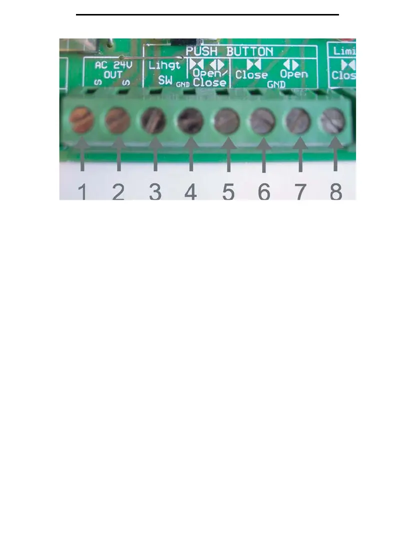
Figure 11
The
receiver wiring to the control board will be set as follows:
Terminal 1: Red wire
Terminal 2: Black Wire
Terminal 3: White Wire
Terminal 4: White and Yellow Wire
Terminal 5: Yellow Wire
Your remotes are set from factory to use Channel 1 (the yellow button in Figure 9), to open and close the
gate, and Channel 2 (the blue button in Figure 9) is to set to control an exterior light.
If you are using a wireless, Multi-Code compatible keypad, please note that you must switch the wires
from Terminals 3 and 5. This will allow the wireless keypad to open and close the gate, but it will
reverse
the factory settings for your remote transmitters channels. Now you must use Channel 2 (the
lue button) to open and close the gate, and Channel 1(the yellow button) to control the exterior light if
ap
plicable.
12