9
5. 8-mm. Allen key
6. Aspiration tube
7. 4 u. tube-cable brackets
8. Screwdriver
9. Oil flask
10. Operating instructions and miscellaneous docu-
mentation
4. OPTIONAL ACCESSORIES AND TOOLS
Hard-metal disk D.165 24z Ref. 7040314, for cutting
wooden doors and skirting boards.
Hard-metal disk D.165 30z Ref. 7040316, for cutting
metal parts, ideally suited for cutting steel sheet for
reinforced doors.
Diamond disk D.150 Ref. 7040193 for direct masonry
cutting. It may be used to cut brick, breeze blocks,
terrazzo, clinker, concrete, granite, ceramics, porcelain
and stoneware.
Side handgrip Ref. 7045728.
5. APPLICATIONS
The RZ270S trimming machine is especially designed to
enable the simple, precise trimming of door bottoms and
skirtings in order to facilitate the installation of all types
of flooring, carpeting and parquet floors without having
to dismount the aforementioned elements.
6. ADJUSTMENTS
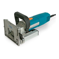
6.1 ADJUSTING THE CUTTING HEIGHT
Unplug the machine from the electrical
outlet before making any adjustments on it.
In order to adjust the cutting height, proceed as follows:
Loosen the screws A (Fig. 1) at the sides of the base with
the service key and adjust to the desired cutting height
by spinning the knobs B (Fig. 1) in the same direction
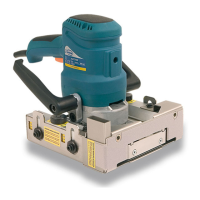
and at the same time. The regulation markings C (Fig. 1
and 2) located on both sides of the base should line up
exactly with the measurement to be cut. Then retighten
the fastening screws.
If the markings C on both sides do not
coincide, the saw will not be parallel to
the base and will cause the machine to
overheat, producing a faulty cut (Fig. 2).
6.2 ADJUSTING THE CUTTING DEPTH
Unplug the machine from the electrical
outlet before making any adjustments on it.
In order to adjust the cutting depth, loosen the screw D
(Fig. 3) with the service key, slide the stop rule E to the
desired measurement and retighten the screw D (Fig. 3).
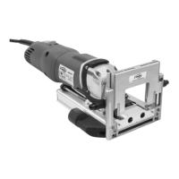
6.3 HANDGRIP POSITION
The two handgrips J may be placed either at an angle to
the base (Fig. 1) or vertically (Fig. 4), whichever is more
comfortable for the user. To change position, loosen
the screws A1 (Fig. 4) and attach the handgrips in the
required position).
7. STARTING UP THE MACHINE
After making the necessary adjustments to the machine,
proceed as follows for its start-up:
- Ensure that there is no type of foreign object obstructing
the saw blade cutting area.
- Plug the machine into the electrical outlet, ensuring
that the power supply voltage coincides with what is
indicated on the machine's characteristics plate.
To start up the machine, push button F (Fig. 1) and then
operate its front lock G (Fig. 1). To stop the machine
press the button “X” (Fig. 1) and the switch will return
to the off position.
8. CUTTING DOOR BOTTOMS, JAMBS AND
SKIRTINGS
After making the necessary depth and height ad-
justments, proceed with cutting as follows:
Start up the machine using the button F (Fig. 1), and
then rest it on the skirting or door to be cut and apply
pressure to the handgrip J (Fig. 1) in the lengthways
direction, sliding the machine on the inside of its guides.
Once it has arrived at the stop set previously, slide the
machine from left to right in order to proceed with
cutting, doing so by applying even pressure; do not
force the advance of the machine, which will cause the
saw to overheat and produce a faulty cut. Once finished
cutting, gradually reduce the pressure on the handgrip,
and the machine will go back to its starting position,
with the blade inside of its protective cover.
Most doors may be cut without being taken off their
hinges. To do this, the door must be fully opened, as
far from the frame as possible, and held in place. It is
recommended that you cut the door from the inside
out, moving away from the hinges. To avoid splintering
veneered or varnished doors, we recommend making a
2 to 3 mm deep initial cut on the entrance face of the
door, so that the outer layer may be cleanly cut. This
should be followed by a further cut as described above.
9. CUTTING CORNERS
In order to perform a corner cut, loosen the screws D
(Fig. 1) and remove the machine's front guide I (Fig.
1). It is advisable to leave this operation until the end
 Loading...