Antenna & Mast
1. Insert the driveshaft into the gearbox and
turn the handle anti-clockwise until the
gearbox has rotated through 90
0
and
is vertical. Now remove the driveshaft.
ASSEMBLY & INSTALLATION
2. Whilst feeding through the coaxial cable,
lower the mast onto the gearbox and
gently over the three O-rings with a
twisting motion, being careful not to
trap or damage the O-rings. If necessary
use a soapy water solution as a lubricant
(DO NOT use anything oil based).
3. Secure the mast with the M5 bolt using
the Allan key supplied.
5. Now slide the whole
assembly down the
mast ensuring the
drive shaft locates in
the gearbox and the
‘H’ indicator is centred
in the window.
6. Once in place secure
with the M5 bolt
using the Allan key
supplied
VERY IMPORTANT –
When fitting the two
M5 bolts, the heads
must be flush with the
mast to prevent
damage to the gaiter.
4. Next ensure the H/V
Indicator is threaded
fully down the threaded
winder handle
mechanism. Then slide
the whole assembly
into the Mast End Cap.
Positioning
When positioning the Antenna & Mast, please
consider the following:-
1. Position in a suitable wardrobe or locker,
away from the edge of the roofline to
reduce the possibility of damage when
travelling.
2. Ensure there is sufficient space to allow
the mast to fully retract.
3. The mast needs to mount against a wall
for fixing of the Wall Bracket.
4. Ensure there are no obstructions on the
roof that would obstruct either the
lowering or rotation of the antenna.
5. Wherever possible, mount on the offside
of the vehicle to reduce the possibility of
collision with overhead obstructions.
6. You must ensure there is enough space
for the mast to retract fully and for the
location of the Amplifier.
7. Position so the Antenna Dome is not
shielded from incoming TV signals when
raised.
8. Check there are no electrical cabl
es
before drilling the mounting hole.
Fitting
You must ensure that there is sufficient
strength in the roof structure to support the
antenna and mast.
To give extra stability and a professional finish
an Antenna Blanking Plate is available should
the antenna you’re replacing have a larger
footprint.
1. Using the enclosed Template against the
ceiling, position the centre of the hole for
the mast 50mm from the wall and drill a
50mm diameter hole. It is crucial that the
mast runs VERTICAL through the roof.
The Amplifier
Positioning & Fitting
1. Locate the Amplifier in the wardrobe or
locker close to the ceiling, adjacent the
mast, where it is easily accessible.
2. Fix in place using the two 38mm screws
Power Supply
1. The Amplifier requires a 12-24 volt power
supply from a fused auxiliary outlet fed
from the battery. If wiring direct to a battery
we recommend an in-line fuse (max 5 amp)
on the positive wire. If unsure please consult
with a qualified installer.
RED STRIPE +VE, BLACK –VE
DO NOT connect into any other 12-24 volt power
cables as they may carry electrical interference
which will cause picture pixillation.
Connecting Up the System
1. Plug the Antenna into the ‘ANT.IN’ socket.
DO NOT secure the cable, which must be
left loose.
2. Plug your lead into the ‘TV’ socket of the
Amplifier and into your TV antenna socket.
3.
Should your TV position be a greater distance
than the fly lead provided you will require
a length of coaxial cable and two coaxial
plugs, which are available from our Vision
Plus Range.
IMPORTANT – Do not over tighten the F-Connectors
when fitting to your amplifier. The same applies
when de-coupling too.
1. Loosen the Mast Locking Collar and Wall
Bracket to raise the antenna.
2.
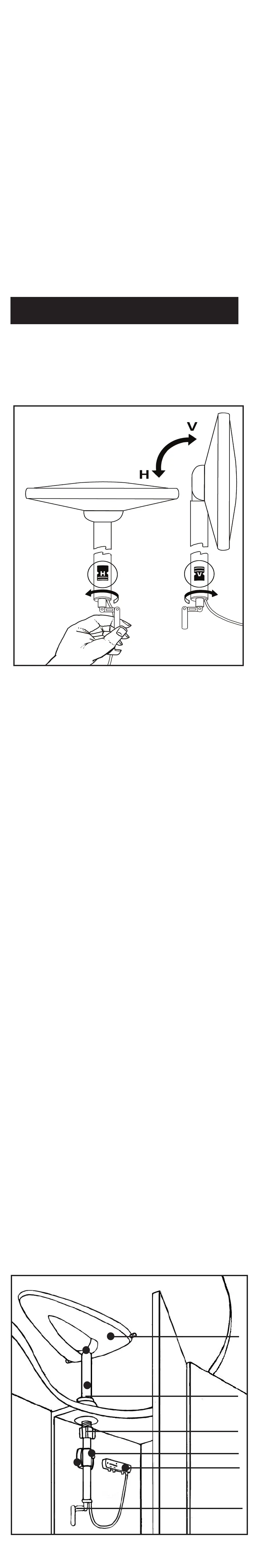
Determine whether the TV transmissions are
horizontal or vertical and position accordingly.
OPERATING THE SYSTEM
Removing the Antenna
A permanently fitted Status can be easily
removed leaving only the Mounting Foot and
rubber gaiter.
1. Unplug the antenna lead from the Amplifier.
2. Loosen the Mast Locking Collar and Wall
Bracket, lift off whilst feeding out the mast,
coaxial cable and plug.
3. Push the Blanking Cap supplied into place.
IMPORTANT - The Blanking Cap is a temporary
seal and is not recommended for long term use.
3. Switch ON the Amplifier and the LED will
illuminate and check the gain is set to MIN
by rotating the button anti-clockwise.
4. Rotate the antenna.
RED – Poor signal - keep turning.
YELLOW – getting better - slow down.
GREEN – Signals located, ready to GO.
5. If there’s no GREEN increase the Gain and
repeat the 360 degree rotation.
6. Once the transmitter has been located
increase the Gain to MAX.
7. Turn on your television set and tune in.
This will be necessary at all new locations.
8. Secure the Antenna by hand tightening the
Mast Locking Collar and Wall Bracket.
IMPORTANT
You may detect more than one transmitter.
Choose the position that gives you the most
channels when tuning in your TV.
In poor signal areas the LED may only glow
YELLOW.
In strong signal areas you may need to reduce
the gain by rotating the Control anti-clockwise.
Antenna Dome
Mounting Foot
Mast Locking Collar
Amplifier
Winder
Wall Bracket
2. On the roof, screw into place the Mounting
Sleeve with foam seal with the four 16mm
screws supplied.
3. On the inside, thread the Locking Plate up
the sleeve to the ceiling and hand tighten.
Secure with the three 16mm screws.
4. Position the Wall Bracket approximately
250mm down from the ceiling and secure
in place with the four 38mm screws supplied.
5. Feed the Antenna and Mast through the
Roof Assembly and the Wall Bracket
and lower into place.
6. Tighten the Mast Locking Collar and the Wall
Bracket to secure.
When looking directly at the H/V window
on
the bottom of the mast you are looking
in the
same direction the antenna is pointing.
DAB & FM Radio Connection
Status is designed to receive DAB & FM when
connected to a radio with DAB/FM facility.
1. This will require a coaxial car radio plug,
coaxial connectors and a length of coaxial
cable, which are available from our Vision
Plus Range www.gradeuk.co.uk
2. Once the cable has been installed plug into
the ‘Radio’ socket of the Amplifier and into
your Radio.
Dependant on location DAB & FM Radio
reception may be improved by setting the
antenna to Vertical.
DO NOT connect into any other 12 volt power
cables as they may carry electrical interference
which will cause picture distortion
Should your external mounting surface be
angled, we have an alternative Adjustable
Mounting Foot that accommodates angles up
to a maximum of 15 degrees.
For more information and availability, please
contact www.visionplus.co.uk or call 0115 986
7151.
ANGLE ADJUSTABLE MOUNTING FOOT
 Loading...