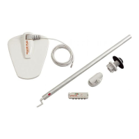
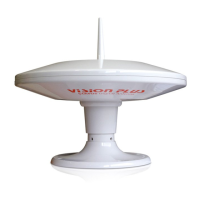
STATUS 560 Digital Antenna System
Please read these instructions carefully. Incorrect
installation will affect the performance of your Status
Dimensions:
Antenna Dome Length 530 mm
Width 340 mm
Height 125 mm
Mounting Foot & Gaiter Diameter 122mm
Height 35 mm
Amplifier
157 x 45 x 29mm
Technical:
Frequency Range UHF 470-860 MHz
FM 88-108 MHz
DAB 175-230 MHz
Antenna Forward Gain 7 db
Amplifier Gain 16 db
Gain Adjustment 15 db
Noise Figure 2.8 db
Output Impedence 75 ohms
Output 92 dbuv
Power Supply 12-24 vDC
Power Consumption 90 ma
Signal Outputs 3 TV 1 Radio
RETAIL
The following are some of the key areas we suggest
you check which generally solve the most common
problems encountered with the operation of the
Status antenna.
Coaxial Connections
It is critical that all connections in the system are
fitted correctly and only quality plugs have been
used.
Coaxial Cable
Sharp bends, kinks and hot surfaces can easily damage
coaxial cable and should be avoided. Coaxial cable,
if placed in close proximity to electrical cables,
transformers or other pieces of electrical equipment,
may pick up electrical interference causing picture
quality to deteriorate, especially in poor reception
areas. Excess cable should be removed and NOT
coiled as this may cause picture distortion. An
inspection of the routing of the cable is highly
recommended to ensure all is correct.
Gain Control
In normal use the button should be rotated
clockwise for maximum. In strong signal areas the
amplification may need to be reduced. To reduce
amplification rotate the button anti-clockwise
until picture quality improves. The button rotates
through 270 degrees from MAX to MIN.
LED Light
Should the LED on the Amplifier not light, firstly
check there is power to the unit. Secondly check the
polarity is correct. Otherwise contact ourselves for
further assistance.
Short Hook Up - Test 1
This test isolates the wiring from the Amplifier
through to your TV/Radio points.
Unplug the coaxial plugs from the ‘TV’ sockets of
the Amplifier and using your TV fly lead with
Convertor 1 supplied. Connect your TV to the
Amplifier.
Please ensure the Antenna Dome is plugged directly
into the ‘ANT-IN’ socket of the Amplifier and switch
on. Tune in your TV for the strongest signal.
If the picture quality improves the fault lies with the
wiring of the system between the Amplifier and the
TV outlet socket.
Short Hook Up - Test 2
This test isolates the Amplifier by connecting your
TV direct to the Antenna.
Fault Finding
MAINTENANCE
Gaiter
We suggest you periodically check the gaiter for
any signs of damage or for wear.
If the rubber is caught by overhead obstructions it
may rip or tear which would allow water to work
its way into the fabric of the roof.
Over an extended period of time the gaiter will
wear at the contact area with the mast. Should the
gaiter begin to fail the signs will be small amounts
of water dripping down the outside of the mast,
however, the design of the Gaiter and Mounting
Foot ensures that water cannot work its way into
the fabric of the roof. Should this problem occur
contact ourselves for a replacement unit.
Spares & Repairs
Should you require any parts for replacements
or repair please log on to www.gradeuk.co.uk or
contact ourselves on 0115 986 7151.
GUARANTEE
The Status Antenna has a return to base guarantee
against defective parts and workmanship for
two years from date of purchase*. This does not
include any malfunction resulting from improper
use, incorrect installation, accidental or malicious
damage. To support your guarantee claim a dated
Proof of Purchase will be required.
*This does not affect your statutory rights. Any queries
concerning warranty please contact ourselves.
Maintenance
cable end. Using your TV Fly lead connect the
antenna directly to your TV. Tune in your TV for the
strongest signal.
If the picture quality improves, the fault lies with
the Vision Plus Amplifier.
Unplug the Antenna from the Amplifier and
connect Convertor 2 supplied to the plug on the
Signal
Action
No picture or sound, TV freezing, severe
pixilation, break up and picture drop out
Moderate pixilation and sound distortion
Minor pixilation, will not receive all
channels
Stable picture, good sound quality, will
receive all channels
Possible pixilation, picture break up and
drop out
No picture or sound, TV freezing, severe
pixilation, break up and picture drop out
Check the amplifier gain is set to maximum (rotate
clockwise). Check antenna alignment which must
be directed at the transmitter. Ensure the antennas
polarity is correct, whether horizontal or vertical.
Bypass the amplifier by following “Short Hook-Up
Test 1”.
N / A
Reduce the amplifier gain (rotate anti-clockwise).
Rotate antenna AWAY from the transmitter.
Rotate antenna AWAY from the transmitter.
Switch ‘OFF’ the amplifier and turn the gain control
to maximum (rotate clockwise).
Very Poor
Poor
Medium
Good
Strong
Very Strong
After performing any of the ‘Actions’ above you must re-tune your TV
Symptom
Position the template in place and drill a
pilot hole from the inside, clean through
the roof. The hole MUST BE VERTICAL.
First drill from the inside using a 50mm
hole cutter.
Next drill from the outside using the same
50mm hole cutter to create a through
hole. File down any rough edges.
TEMPLATE FOR HOLE CUTTING
50mm
Antenna Dome Co-axial Cable
Check the routing of the coaxial cable from the
Antenna Dome to the Amplifier. Check to ensure
there are no kinks or trapped cable or if there are
loops of surplus cable which could be affecting
performance.
Customer Help Line
Should you still be experiencing difficulties and
require assistance, please do not hesitate to
contact us at the address below.
You must ensure that there is sufficient
strength in the roof structure to support the
antenna and mast.
Travelling
When positioning the Antenna Dome please
allow for the following:-
DO NOT TRAVEL:-
• WiththeAntennaraised
• WiththeAntennasetforverticalsignals
To reduce the possibility of damage when
travelling, have the antenna pointing towards
the rear of your caravan/motor home.
Routing Coaxial Cable
Coaxial Cable is quite fragile and must be
handled with care. Please comply with the
following as failure to do so will severely affect
performance.
1.
Do not crush, kink or over-bend the coaxial
cable which has a minimum bend radius of
25mm.
2.
Any excess cable should be removed and
MUST NOT be coiled.
3.
Avoid increasing the number of
connections or breaks in the coaxial
cable as they will reduce performance,
especially in weak signal areas.
4.
Do not run coaxial cable next to mains
cable, leave a minimum distance of
120mm to prevent interference.
5.
Do not allow the cable to come into
contact with any hot surfaces as this could
melt the insulation of the cable.
6.
Keep away from fluorescent lighting.
7.
Do not add excessive lengths of coaxial
cable, this will result in increased signal
losses and a reduction in picture quality.
8.
Should the cable need to be lengthened,
use high quality cable and connectors
which are available from our Vision
Plus Range through our dealers or directly
from ourselves at www.gradeuk.co.uk.
IMPORTANT GUIDELINES
VISION PLUS
8 Finch Close
Lenton Lane
Nottingham NG7 2NN
0115 986 7151
info@visionplus.co.uk
www.visionplus.co.uk
VISION PLUS is a trading name of Grade UK Limited