DE6205 3
7DPSHU6ZLWFK7$03RSWLRQDO
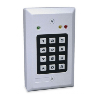
This option includes a terminal block and a tamper switch on a
separate PC board. The tamper switch can be used in two ways:
1. To protect the CL-8 if tampering is attempted by removal of
the front of the case. In this configuration, the tamper actuator
remains within the case, in physical contact with the inner
surface of the keypad's back box.
2. To protect the CL-8 if tampering is attempted by removing the
unit from the wall or by removing the front of the case. This is
accomplished by opening the tamper actuator knockout in the
back box, allowing the tamper actuator to extend out of the
back box and contact the wall.
Note:
the tamper switch is delivered as a separate item. It is not
installed at the factory. When ordering, specify TAMP-1.
Figure 4. Tamper Switch Installation
352*5$00,1*352&('85(6
,QWURGXFWLRQ
Programming the keypad is, in simple terms, providing it with a set of
instructions on how to react in various contingencies. The keypad
must be programmed as soon as all installation and wiring have been
completed. Later on, as changes take place, partial or full
reprogramming may be carried out as many times as necessary.
The first step in "telling the keypad what to do" is to access the
programming menu, which is accessible only by use of the current
"master code". The factory default master code is 1234, but after
subsequent programming, this default code will be automatically
superseded by user code No. 01, which is the real master code.
Important! Experienced programmers may refer directly to
Appendices A and B at the end of this manual.
Caution: User code No. 01 must be kept secret at all times to
prevent the introduction of unauthorized changes in the keypad's
programming. Do not use this code for normal entry
into the restricted area.
3URJUDPPLQJ7LSV
)LJXUH
A.
The programming menu is selected by keying **1234** (1234 is
the factory default master code). The Green LED will
acknowledge (by flashing slowly) that the programming menu
is
now active.
B.
While the programming menu is active (green LED flashes
slowly), you can select various programming functions by
pressing a number from 1 to 5 (Table 1).
C.
Entering a function number while the green LED is flashing
slowly causes the green LED to start flashing rapidly. The
desired value should then be entered, followed by the "end-of
data" character
#
.
D.
Functions 2, 3 and 5 on the menu are single-stage
programming operations. If the correct data is entered,
followed by
#
, the green LED lights steadily for 2 seconds and
then resumes flashing slowly (indicates return to the menu).
E.
User Code programming (Function No. 1 on the menu) is a
4-stage operation which calls for step-by step entry of several
data groups in succession (see Table 2 below). The first 3
data groups are each terminated by pressing
#
which
serves here as a "separating character". The last data group
is also followed by keying #, which resumes its role as an
"end-of-data" character.
F. Deleting user codes (function No. 4 on the menu) is a
two-stage programming operation (see Table 3). The first data
group is terminated by pressing #, which serves here as a
separating character. The second group is the master code
followed by #, which resumes its role as an "end of data"
character.
Table 1. Programming Menu
No. Function Name Value to enter Description
1
Programming user codes Any combination up to
8 digits
Each code entered is assigned to an authorized individual or to a group of
people (Programming Chart - Appendix A)
2
Timing the relay
01 to 98
Sets relay contact closure duration between 1 and 98 seconds
Latching the relay
99
Selects toggle mode (latching/unlatching)
3 Selecting AUX output mode 1 to 7 Each number entered selects a different
AUXILIARY
output operating mode
(Table 4)
4
Deleting a single user code
user numbers, 02 to
56 + [master code]
User code corresponding to the user number entered is deleted.
Deleting all user codes
# + [master code]
All user codes are deleted in a single operation, except for master code 01
5
Ambush digit
0 to 9
The programmed digit will be valid until deleted or replaced
Delete ambush digit
The ambush digit is canceled
Table 2. User Code Programming Steps
Step Enter Description
1 1,[user no.] # 1
selects the user-code programming function;
[user no.]
is any number from 01 to 56.
2 [user code] # [user code]
is the individual code assigned to the user, from one to eight digits, each digit a number from
0
to
9
.
3 [user code] # [user code]
repeats the previous step for verification
4 [trip code] # 1
to trip only the relay, or
2
to trip only the
AUX
output, or
3
to trip both the relay and the
AUX
output.
 Loading...