DE6217 1
&/
Outdoor/Indoor Access Control Keypad
Installation Instructions
,1752'8&7,21
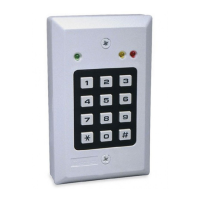
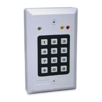
The CL-80 is a versatile, weather-resistant digital keypad, designed
for outdoor and indoor use. Possible applications include access
control, electrical switching, and security system arming and
disarming.
User access codes ensure that all functions controlled by the CL-80
are restricted to authorized persons only, and each code can be
assigned its own privilege level.
To improve access management, the CL-80 responds to 56 different
access codes - each allocated to a single user or a group of users.
Each of the 56 different access codes may be programmed to energize
either the built-in relay, or the auxiliary output, or both.
Programming is easily carried out via the keypad, and access codes can
be individually added, deleted, or the levels of control revised at any time.
Only the MASTER CODE holder has the privilege to program the unit.
In addition to a 10 A on-board relay, an auxiliary open-collector output with
7 operating modes can be programmed to control additional devices.
A simultaneous dual keystroke action activates the PANIC output, which
can be used to trigger a silent alarm in emergency situations.
63(&,),&$7,216
Code composition: Any combination, 1 to 8 digits
Keypad type: 12 keys in 3 X 4 matrix, tactile operation
Operating voltage: 9 -16 or 22 - 26 V AC/DC - selectable
Current drain: 15 mA standby, 55 mA with relay and AUX. Output
active
Power failure immunity: EEPROM retains all programmed
information even during total power loss
Relay contact rating: 10 A/28 VAC or DC
Relay pull-in: Programmable 1 – 98 seconds, or toggle mode (latch /
unlatch)
Current sinking capability of AUX. and PANIC outputs:
Up to 100 mA (protected by an 18 ohm series resistor)
LEDs: Green indicates keypad status
Red and yellow are available for optional indication (as required) and
have 1 k ohm series resistors connected.
Operating temperature:
-20
°
C to 65
°C
(
-4°
F to 149
°F)
Index of Protection: Meets IEC529:1989 requirements for IP54
(protection against dust and sprinkled water)
Dimensions: (W X H X D): 8.2 X 12.2 X 3.1 cm
( 3-1/2 x 4-13/16 x 1-1/4 in)
Weight: 200 g (7.14 oz) including rubber gasket
Tamper switch:
The dual function tamper switch is designed to
detect attempts to open the unit, or remove it from wall.
,167$//$7,21
0RXQWLQJ
Select a suitable mounting location with a stable flat surface.
Remove the case closure screw from the bottom edge of the keypad,
and remove the keypad assembly from the base. Hold the base in
position and mark the 3 screw locations for drilling.
Note: The Tamper switch will be activated if the front part of the
keypad is removed and also if the base is forced away from the wall.
This is achieved by incorporating a breakaway tab at the bottom right
corner of the base (see Figure 1). It is therefore especially important
to firmly attach this tab to the wall with a long screw.
Fit the base into the rubber gasket and use the 3 mounting screws to
attach the base and gasket to the selected surface
Figure 1. Base and Rear Sealing
Gasket
Figure 2. Front Casing and Circuit Board
:LUH*DXJHVDQG5RXWLQJ
Use # 20 AWG or larger for connections between relay and door
strike, control panel or other switching devices. All other connections
are to be made with # 22 AWG or larger. Route the wires through
the slot in the rubber sealing gasket and the recessed entry channel
in the keypads base. Avoid contact between uninsulated wires and
the printed circuit board.
&RQQHFWLRQV
IMPORTANT! Before wiring, set jumper JP3 in the position
that corresponds with the power source you are using: