2 DE3191
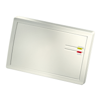
TROUBLE indicator: This LED is extinguished while all is well,
but lights steadily for as long as the TAMPER, LOW BATTERY
and INACTIVITY outputs are activated.
The trouble indicator will remain lighted until all trouble is cleared
(restore/attendance messages arrive from all trouble sources).
Note: Both indicators have other functions during a learning
session (see Paragraphs 3.5 and 3.6).
63(&,),&$7,216
RF SECTION
Front-End Module: Superheterodyne UHF receiver.
Operating Frequency: Per local requirements in country of use.
DATA PROCESSING SECTION
ID codes: Over 16,000,000 possible 24-bit combinations.
Total Message Length: 36 bits (66 bits for code secure devices)
ID Learning Capacity: 112 different ID codes
Expander Bus: 4-wires (12V+, [–], DATA and COMMON)
ELECTRICAL DATA
Zone Outputs: 4, up to 100 mA each, open-collector type
Status outputs: 4, up to 100 mA each, open-collector type
Output Polarities: N.O. or N.C., selected with DIP switch
Output No. 1 modes: Pulsed (2 seconds) or toggle, selected
with DIP switch
Tamper Switch Ratings: 0.1 A / 30 VDC.
Input Voltage Range: 10.5 - 16 VDC
Current Drain (@ 12 VDC): 45 mA
PHYSICAL
Operating Temperatures: 0°C to 49°C (32°
F to 120°
F).
Dimensions
(H
x
W
x
D):
108
x
165
x
38
mm
(4-1/4
x 6-1/2
x
1-1/2").
Weight (including rigid antenna): 214 g (7.5 oz).
Compliance with Standards: Designed to meet FCC part 15,
ETS 300-220, ETS 300-683 and MPT 1340 requirements.
AUXILIARY EQUIPMENT
MCX-8: Eight-output zone expander unit.
352*5$00,1*
+HOSIXO+LQWV
A learning session is required to let the MCR-308 learn the ID
codes of individual wireless transmitters and link each transmitter
to a specific output (up to 4 transmitters per output).
In addition, it is necessary to register in the receiver’s memory the
ID code of any MCX-8 expander used in the system. If these
codes are not “learned”, the expanders will not function.
The quickest way to conduct a learning session is on a work
bench, with every transmitter you need within reach, and where
you may observe the receiver’s indicator LEDs and listen to the
buzzer.
,QLWLDO6WHSV
A. Remove the screw that secures the cover to the base and
remove the cover as shown in Figure 4.
Figure 4. Removing the Top Cover
B. The semi-rigid antenna supplied with the MCR-308 is taped to
the inner part of the cover. Detach the antenna from its
storage position, insert its straight tip into the antenna terminal
and tighten the screw well. See Figure 2 for antenna
terminal location.
C. Gather up all transmitters used in the system and mark each
one according to the desired deployment plan.
D. Temporarily power up the MCR-308 by connecting a 12 V
battery or a 12 VDC power supply across its 12 V input
terminals. Observe polarity!
6HOHFWLQJWKH7DUJHW=RQH2XWSXW
In order to link a transmitter to a specific zone output, you must
first select the desired output number by setting DIP switches
SW1 through SW-5 as shown in Table 1. A (–) sign indicates an
off position of the switch.
Table 1. Output Selection Chart
Zone
DIP Switches Wired
Output #
1 2 3 4 5 Output Selected
MCR-308
1
ON
––––
Output No. 1
2
–
ON
–––
Output No. 2
3
ON ON
–––
Output No. 3
4
––
ON
––
Output No. 4
1
ST
EXPANDER
5
ON
–
ON
––
Output No. 1
6
–
ON ON
––
Output No. 2
7
ON ON ON
––
Output No. 3
8
–––
ON
–
Output No. 4
9
ON
––
ON
–
Output No. 5
10
–
ON
–
ON
–
Output No. 6
11
ON ON
–
ON
–
Output No. 7
12
––
ON ON
–
Output No. 8
2
ND
EXPANDER
13
ON
–
ON ON
–
Output No. 1
14
–
ON ON ON
–
Output No. 2
15
ON ON ON ON
–
Output No. 3
16
––––
ON
Output No. 4
17
ON
–––
ON
Output No. 5
18
–
ON
––
ON
Output No. 6
19
ON ON
––
ON
Output No. 7
20
––
ON
–
ON
Output No. 8
3
RD
EXPANDER
21
ON
–
ON
–
ON
Output No. 1
22
–
ON ON
–
ON
Output No. 2
23
ON ON ON
–
ON
Output No. 3
24
–––
ON ON
Output No. 4
25
ON
––
ON ON
Output No. 5
26
–
ON
–
ON ON
Output No. 6
27
ON ON
–
ON ON
Output No. 7
28
––
ON ON ON
Output No. 8
6HOHFWLQJ6XE=RQH/RFDWLRQV
Each zone output is divided into 4 sub-zones, and each sub zone
accepts one transmitter ID. Sub zone locations may be selected
in ascending order from 1 to 4, by clicking the MCR-308’s tamper
switch (a short beep will sound upon each click).
The yellow LED will indicate the ordinal number of the selected
sub-zone location by a flashing sequence as demonstrated in the
following chart:

 Loading...