English
Wireless CodeSecure™ Two-Way Keyfob Transmitter - User Guide
Español
Mando Bidireccional Inalámbrico CodeSecure™ - Manual de Usuario
Portuguese
Comando Bidirecional Sem Fios de CodeSecure™ - Manual do Utilizador
MCT-237
ENGLISH
1. INTRODUCTION
1.1 Description
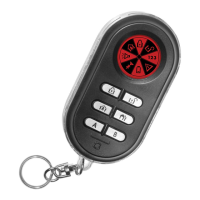
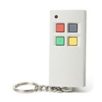
The MCT-237 is a miniature CodeSecure™ 6-button keyfob transmitter,
designed for use with the PowerMax Pro, PowerMaxComplete,
PowermaxExpress unit. The device enables the user to arm/disarm the
alarm system and to view system status.
For each control panel, a maximum of eight MCT-237 keyfob devices
may be enrolled. Operating power is obtained from an internal 1.5 V
alkaline battery. Each transmitter is supplied with a small key ring.
Transmission is initiated by pressing any one of the six pushbuttons.
Upon pressing a specific button, the keyfob transmits a
CodeSecure™ digital sequence identifiable by the PowerMax unit,
and a 4-bit function code associated with the button that was pressed.
The next time a button is pressed, the keyfob will transmit a digital
sequence of three transmissions that differs from the one used in the
previous transmission and the respective function code. As a result,
malicious “code grabbing” is virtually impossible.
The MCT-237 includes an optional partition feature. Partitioning allows
you to have up to three independently controllable areas with different
user codes assigned to each partition or one user code assigned to up
to three partitions. A partition can be armed or disarmed regardless of
the status of the other partitions within the system.
Note: The Partition feature appears only if Partitioning is enabled via
the control panel.
The main features of the MCT-237 are:
• Status, alarm
memory, and trouble data retrieval from the control
panel.
• Visual indications by LCD icon display.
• LCD backlighting activation.
• Various audible signals sounded by the speaker in response to
specific actions.
• 1.5 Volt Alkaline battery.
1.2 LCD Icons
The following table provides definitions for each of the eight icons that
appear on the LCD display.
Icon
Definition
Lights steadily when the system / a system partition is in
Arm Home mode.
Flashes when the system / a system partition is in
progress of an exit delay.
Lights steadily when the system / a system partition is in
Arm Away mode.
Flashes when the system / a system partition is in progress
of an exit delay
When the system / a system partition is in progress of an
entry delay both arm and home icons flash.
Lights steadily when the system / a system partition is
disarmed.
Lights steadily to indicate a system partition or a
combination of up to three system partitions.
Lights steadily when a trouble state is detected within the
control panel / a system partition.
Lights steadily when the battery must be replaced without
delay. A “low battery” report is transmitted with the
outgoing digital message.
Lights steadily when there is a communication failure
Flashes when the alarm has been activated or if there is a
memory condition.
1.3 Selecting a Partition / Partitions and
Partition Status
The MCT-237 two-way wireless keyfob is used to control single or all
partitions.
Arming/Disarming All Partitions
To arm/disarm all partitions, press the HOME / AWAY / DISARM
button on the keyfob.
Partition Status and Arming/Disarming a Single Partition
Press the PARTITION STATUS button on the keyfob once; the
display reads the status of the partition. In this state repeated
pressing of the PARTITION STATUS button will display the status of
the enabled partitions and Partition All. To arm/disarm the desired
partition(s), press the HOME/AWAY/DISARM button.
Note: When displaying all partitions, the various statuses of partitions
are displayed simultaneously.
2. SPECIFICATIONS
Frequency (MHz): 315, 433, 868.95 or according to local requirements.
Modulation: ASK (ON-OFF keying)
Coding: CodeSecure
Transmission Range: The transmission range depends on the
sensitivity of the receiver. When the MCT 237 is used with Powermax
Express @ 315 MHz, the typical line of sight reception range
according to UL testing requirements is up to 55 m (180 ft).
Battery: 1.5 V AAA alkaline battery, type GP or equivalent.
Current Consumption: 85 mA during transmission.
Battery Life Expectancy: 2 years (for typical use).
Note: If transmission is still possible despite the battery condition, the
unit will send a low battery signal to the receiver.
Control Functions: Home Arming, Away Arming, Disarming, System
Partition/Status, AUX 1 and 2
Operating Temperature: -10° to 55°C (14° to 131°F).
Dimensions: 75 x 38 x 18 mm (2-15/16 x 1-1/2 x 11/16 in.).
Weight (including battery): 36 g (1¼ oz).
Color: Black
Compliance with Standards: CE/RTTE and EN 50131-1 Grade 2,
Class II
USA: (FCC) CFR 47part 15, UL 1023, UL 985, UL 1635, UL 1637
Canada: RSS 210, ULC S545-02, ULC C1023,CSA C22.2#205
3. TESTING AND MAINTENANCE
3.1 Testing a New Unit
Since the keyfob transmitter is supplied with the battery already
installed, the unit is practically ready to be tested.
IMPORTANT! Before testing, "teach" the control panel the ID code
of the keyfob, as instructed in the control panel Installer Guide.
A. Stand near the control panel and press the keyfob button marked
with a closed padlock icon.
B. Make sure that the control panel responds as programmed and as
stated in the Installer Guide.
C. Operate the keyfob from various locations within the area covered
by the receiver to determine "dead" locations, where transmission
is blocked by walls and large objects, or affected by structural
materials. For optimum operation, point the keyfob directly toward
the control panel.
Note: If dead/marginal zones are a problem, relocating the control
panel may improve the performance.
3.2 Replacing the Battery
Caution! Risk of explosion if battery is replaced by an incorrect type.
Dispose of used batteries according to the instructions.
The battery should be replaced upon receiving a low battery LCD indication.
A replacement 1.5 V AAA alkaline battery, such as GP (or equivalent),
should be used. Replace the battery as shown in figure 2 & 3.