D-302182 PGM-5 Installation Instructions 3
Front unit
Back unit
POWERMAXEXPRESS
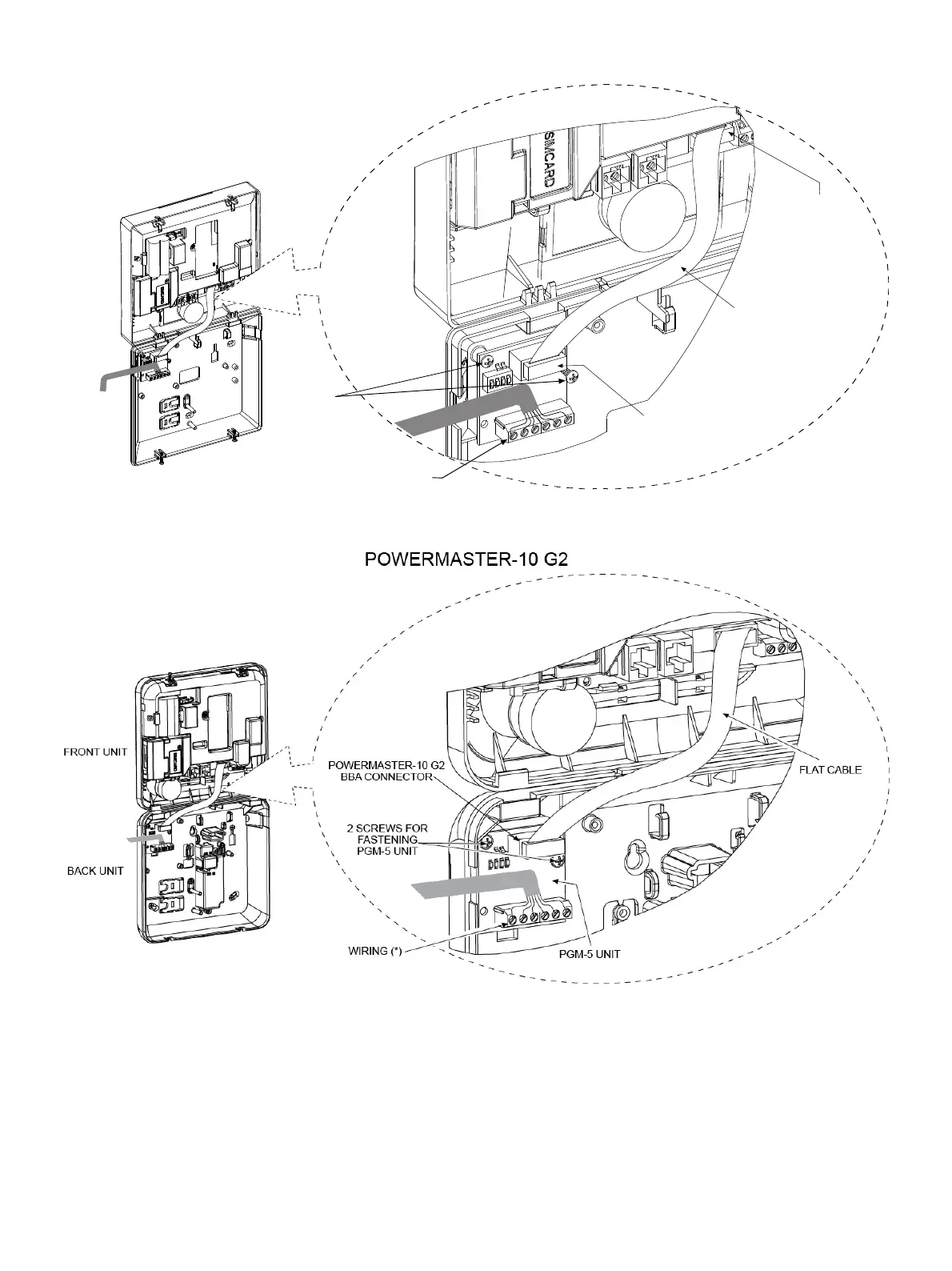
Connect one side of the flat cable into the
PGM-5 connector and the other side into the
PowerMaxExpress BBA connector
PGM-5
PowerMaxExpress
BBA Connector
Flat cable
Wiring*
Screws for
fastening
PGM-5
module
Figure 4c – PGM-5 Mounting and Wiring in PowerMaxExpress Control Panel
* It is strongly recommended to route the cable as shown to prevent interference which may occur if routed too close to the control panel's antennas.
Figure 4d – PGM-5 Mounting and Wiring in PowerMaster-10 G2 Control Panel
* It is strongly recommended to route the cable as shown to prevent interference which may occur if routed too close to the control panel's antennas.

 Loading...


