19ENG
• IM CL
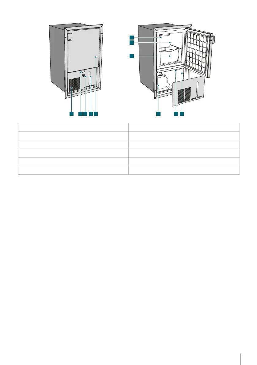
A) Front panel G) Ice level indicator
B) Switch H) Ice tray
C) Adjustment thermostat I) Condenser
D) Water level indicator (only rell) J) Filler (only rell)
E) Front door K) Tank (only rell)
F) grid assembly
5. INSTALLATION
Make sure that the machine is not damaged in any way. Any damages caused during
transport must be communicated to the retailer in due time and in any case, no
more than 24 hours from the time of delivery. Handle the machine with the utmost
care and attention.
Always position the ice maker on a horizontal, at surface.
The ice maker must be positioned in a dry area, well away from any sources of heat.
Sucient ventilation must also be guaranteed and, if the machine is to be boxed in,
two openings must be made in its containing unit: the rst opening must be made
in correspondence to the slits on the front panel ; the second opening must be
aligned with the front or - preferably - the upper part of the furniture unit.
These openings must be no less than 300 sq. cm. If it is not possible to carry out this
operation, then a gap of at least 50 mm must be le between the top of the ice
maker and the surface above it (see annex 2).
Leave the machine idle for at least one hour before putting it into operation. During this
time, it is possible to carry out the initial cleaning operations.
F
G
H
A I KJB C D E