5 6 7 8
ON/OFF pushbutton will alter the output from low to high. Always start
with the low setting and switch to high if it is not possible to detect a
stable reading on the receiver. Using the low setting will also prolong
the battery life.
If unsure of the quality of connection to the service, set the
frequency of the receiver to match the transmitter, hold the receiver
over the direct connection lead and remove and connect the red
lead from the utility. There should be a great change in signal
received. If not improve the grounding or improve the connection to
the pipe or cable. A fast beeping sound indicate a good connection.
To trace the cable use the same method as described in the
Locating a Cable in the Power (50/60Hz) Mode Section.
Depth Measurements
(Available in 8.19 kHz mode only)
To take a depth measurement pinpoint the position and direction as
previously described. Now hold the locator vertically and in line with
he cable or pipe.
Now press the depth measurement/frequency selection button.
There will be a short delay before a depth estimate will be displayed.
NOTE
The depth measurement is an approximation. Depth
indications can be effected by field distortion caused by
adjacent utility lines or changes in direction and depth.
Always use depth measurements as an aid to line
verification but NEVER use them to decide if
mechanical digging is safe. Always dig with care.
An aid to determining if the depth is correct is to repeat a depth
measurement with the locator a known distance (for example 1ft)
above the ground and to note if the depth has increased by this
amount. If it is different from what is expected treat the data as
suspect.
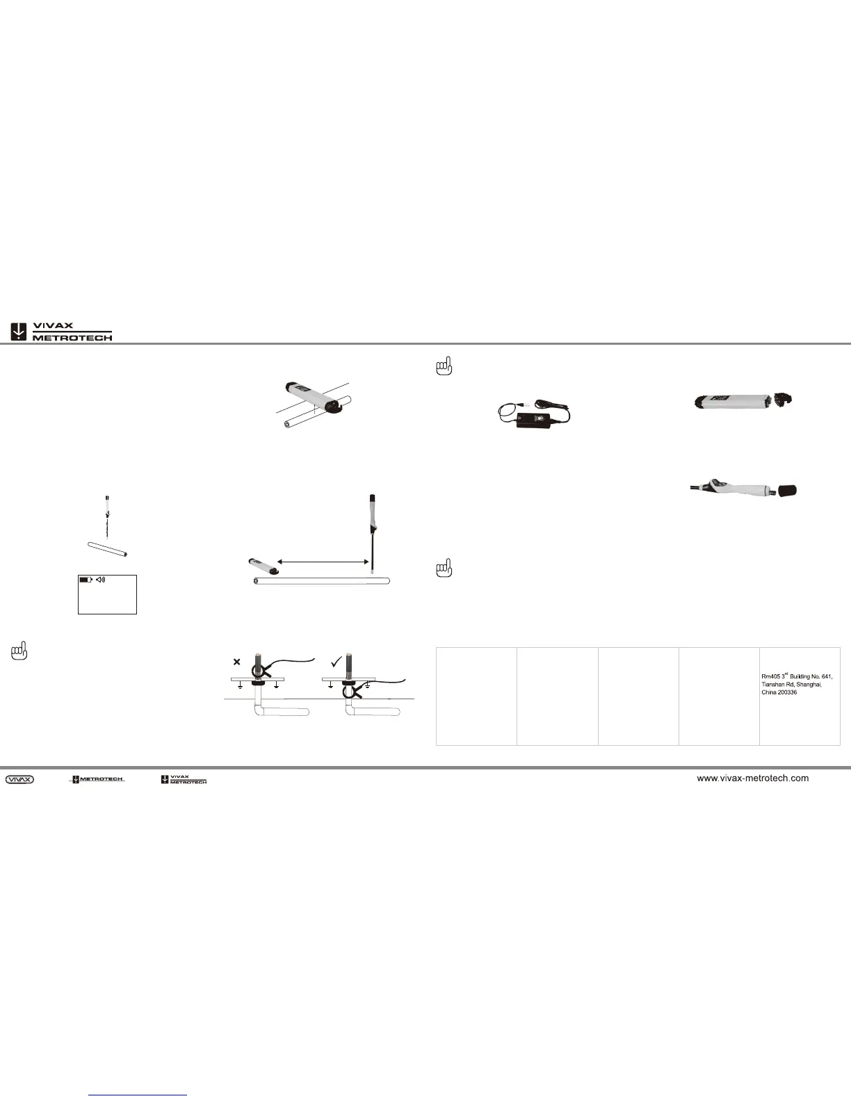
Induction Mode
The induction mode is useful in situations where access to a cable
or pipe is not possible. Remove the direct connection leads so that
the transmitter automatically sets itself into the induction mode.
Place the transmitter over the suspected position of the target utility
line as below.
Switch on the transmitter and set the output to low output. Only
switch to high if the signal received is too low. Only the high
frequency is available in induction mode.
Start locating the line a few paces from the transmitter. Starting too
close will be difficult as the signal radiated through the air from the
transmitter will be greater than that from the cable. Trace the cable
in the normal way.
Signal Clamp Mode
1. Connect the signal clamp to the transmitter.
2. Place the clamp around the cable to be energised. Ensure that
clamping is done below the earthing point of the cable
otherwise a signal will not be induced efficiently.
3. Make sure the two halves of the clamp close properly.
4. Switch on the transmitter and follow the locating instructions as
in Direct Connection Mode.
NOTE
Using the clamp does NOT require a ground connection
from the transmitter. However, the signal quality will be
better if there is a ground at both ends of the cable.
LPC Separation Filter
The LPC separation filter is used to safely inject a trace tone to a live
cable via a domestic mains socket, so that the cable can be traced
from the premises to the connection in the street. It is suitable for
connecting to voltages between 100V AC and 250V AC.
Method:
1. Plug the LPC into the output socket of the transmitter.
2. Identify a suitable main socket. If a switch is fitted to the socket,
switch off.
3. Plug in the LPC to the mains socket and then switch back on.
4. Set the LPC rotary switch to match the two indicator lights.
5. Set the transmitter to the frequency to be located.
6. Locate the line as described in the section Direct Connection
Mode.
NOTE
A transmitter ground connection is not required with
this method as the ground is made within the mains
socket.
Changing Batteries
Transmitter
1. A low battery is indicated by a flashing ON/OFF led.
2. To replace the batteries unscrew the two retaining screws on the
end of the transmitter. Remove the battery cover and take out
the old batteries.
3. Replace with four D type alkaline batteries.
4. Always replace all the batteries. Having batteries with different
charge may result in batteries being reverse polarised which
may then leak or overheat.
5. Replace the battery and hand tighten the retaining screws.
Receiver
1. A low battery is indicated by the icon of the receiver display.
2. To replace the batteries unscrew the end cap on the handle end
of the VM-540/VM-550.
3.
Remove and replace BOTH batteries with fresh 1.5V alkaline AA
(LR6).
4.
Replace end cap.
Service Center Information
If the equipment does not function properly, replace the batteries as
described above. If the equipment still malfunctions, contact one of
the Vivax-Metrotech Customer Service departments, or call the
factory for the nearest authorized Vivax-Metrotech repair station.
Disclaimer: Product and accessory specification and availability
information is subject to change without prior notice.
2 feet 7 inches
8.19k
30 paces minimum
USA
Vivax-Metrotech Corp.
3251 Olcott Street,
Santa Clara, CA 95054, USA
Tel: +1-289-846-3010
Fax: +1-905-752-0214
sales@vxmt.com
www.vivax-metrotech.com
CanadianSales@vxmt.com
www.vivax-matrotech.com
Canada
Vivax Canada Inc.
400 Esna Park Drive,
Unit 17, Markham,
Ontario, L3R 3K2, Canada
Tel: +86-21-5187-3880
Fax: +86-21-5168-5880
info@leidi.cn
www.leidi.com
China
Leidi Utility Supply
(Shanghai) Ltd.
Tel: +49-9544-680
Fax: +49-9544-2273
service@sebakmt.com
www.sebakmt.com
Europe
SebaKMT Seba
Dynatronic Mess-und
Ortungstechnik GmbH
Dr.-Herbert-lann-Str. 6,
96148 Baunach, Germany
T/Free: +1-800-446-3392
Tel: +1-408-734-1400
Fax: +1-408-734-1415
Australasia
SebaKMT AUS
Unit 1, 176 South Creek Road,
Cromer NSW 2009, Australia
sales@sebakmtaus.com
service@sebakmtaus.com
www.sebakmtaus.com
Tel: +61-2-9972-9244
Fax: +61-2-9972-9433
Changes or modifications not expressly approved by the party
responsible for compliance could void the user's authority to operate
the equipment.
Note
 Loading...