2. Attach the RED lead of the direct connect lead to an electrical clean metallic part
of the targeted conductor.
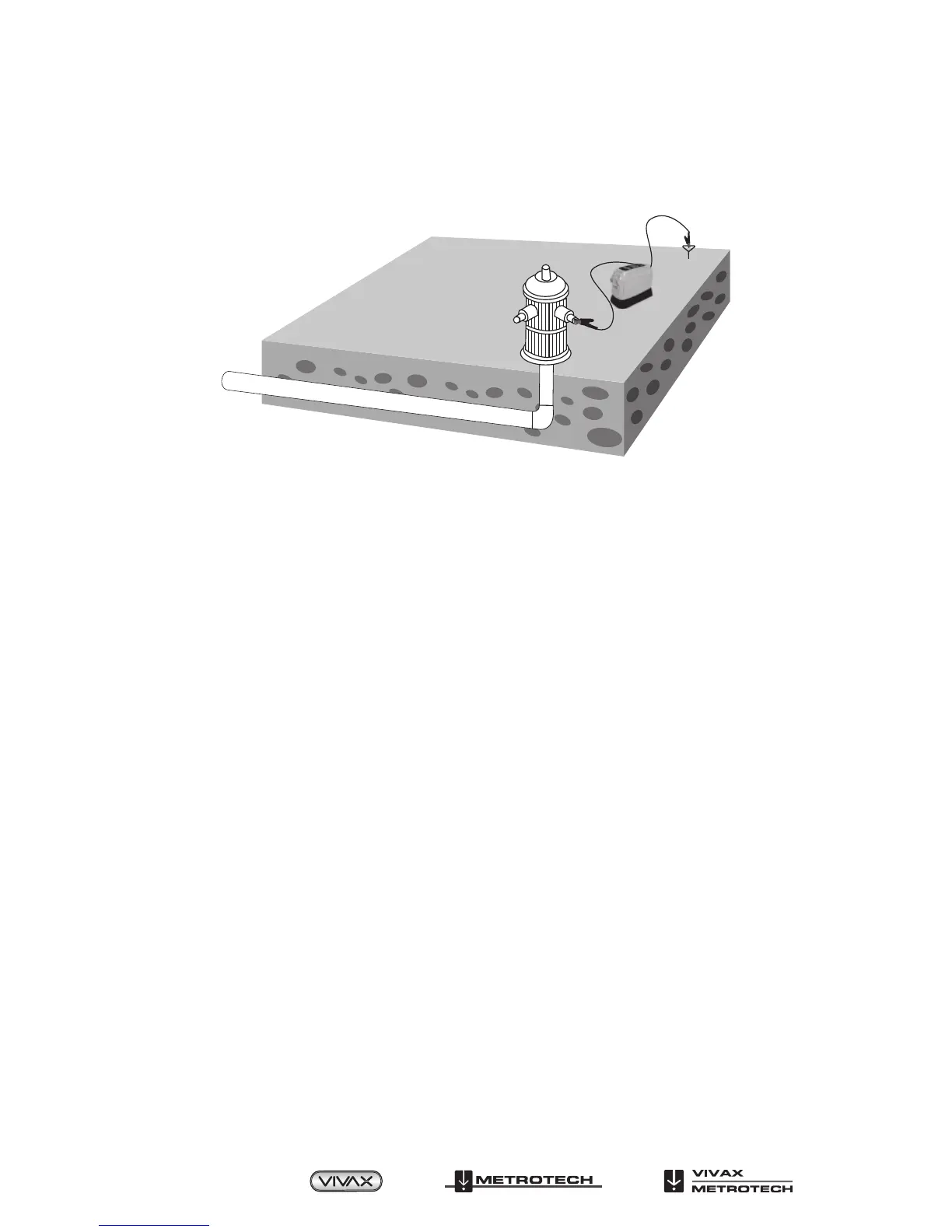
3. Move the transmitter away from the conductor in a right angle direction as shown
below.
Direct Connection
4. Extend the BLACK lead of the direct connect lead as far as possible from the
Transmitter, maintaining the right angle orientation. At this point, push the ground
stake into the ground as far as possible, and attach the BLACK lead to it.
5. Press the ON/OFF button on the transmitter to switch ON.
6. Trace the signal with the receiver.
5.2 Transmitter – Inductive Coupling
Use this method if Direct Connection is not possible, but you can position a signal
clamp around the conductor you want to trace. The Inductive Coupling method uses
a signal clamp to induce a signal onto the conductor when direct metallic contact is
not possible. The clamp is placed around the target conductor. The Transmitter then
induces a signal through the clamp.
For best results, when using the signal clamp, the conductor should be well grounded
at both ends. When tracing lines that have insulators, it is best, but not essential, that
the insulators be bypassed using jumper cables. Bonding and grounding at termination
is often “standard practice” in industries that use cable, but do not assume this to be
the case.
1. With the Transmitter OFF, plug the signal clamp cable into the direct/signal clamp
jack.
2. Place the signal clamp around the conductor, below the electrical ground. See
graphic below. Make sure that the clamp jaws are completely closed.
3. Follow steps 3-6 Direct Connection.
4. Trace the signal with the Receiver.
Page 16 of 35
™
 Loading...