11
English
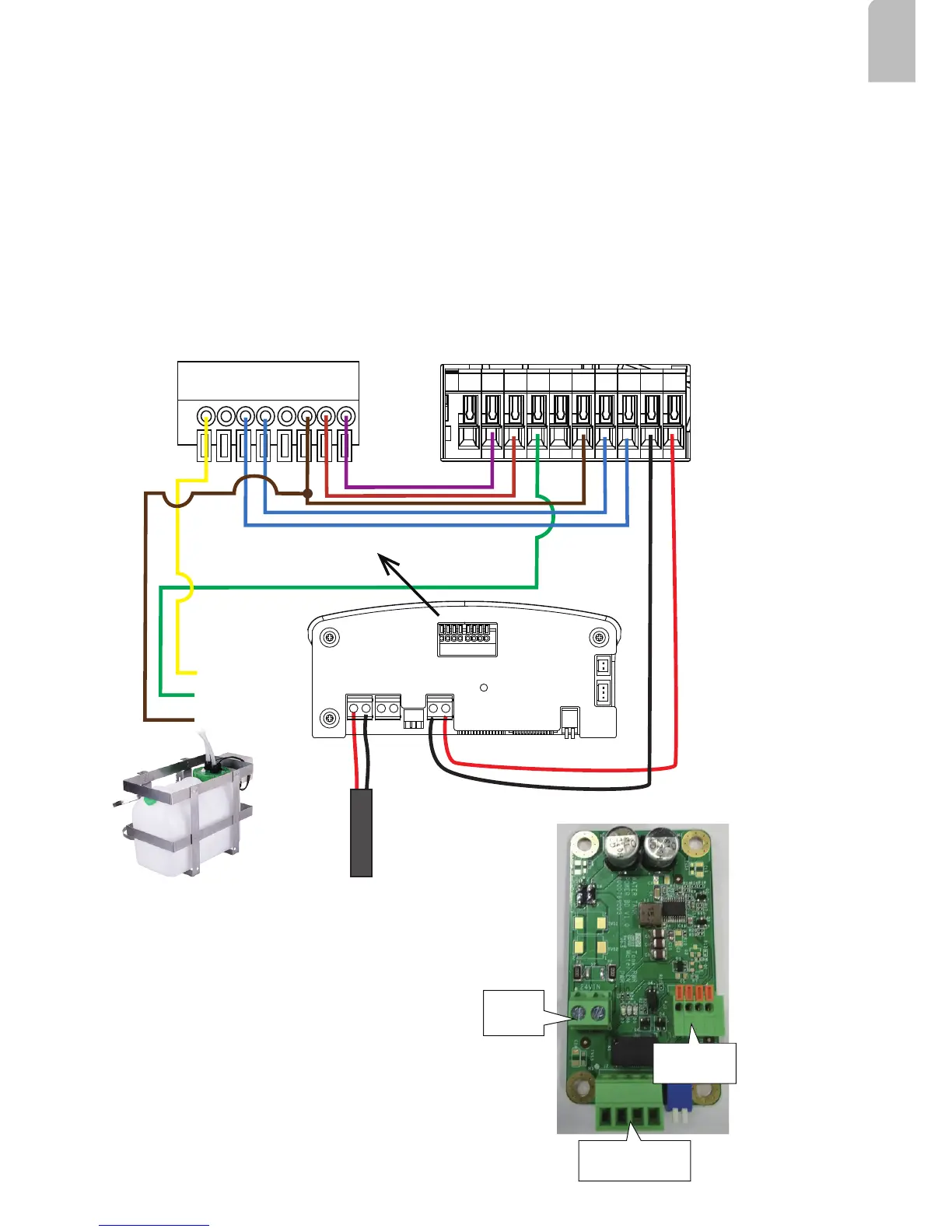
6.
Connect the DI/DO signal lines from the distribution board, if applied, to the camera's
terminal block.
The day/night mode DI connection enables the synchronization of IR light and the
automated day/night switching mechanism on the camera.
DO+
DO-
DI1+
DI2+
DI3+
DI-
RS485-
RS485+
AC/DC pwr
AC/DC pwr
AWG20
AWG26
AC24V
DO2
DI2
DI-
RS485-
RS485+
DO1
DI1
DO+
DC12V
Tank ctrl
Wiper ctrl
GND
IR LED
IR ctrl
5V VCC
Tank ctrl
Tank low water
GND
Tank w/ pump
A sample connection diagram consisting of a housing with IR illuminators and the IP816A
camera is shown below. Please refer to your camera's documentation if your camera
comes with different pinouts.
AC/DC 24V IN
1. Pump motor ON/OFF
2. GND
3. Water level detector Low/high
4. GND
pin 1
pin 1
1. Water tank EN
2. Water low level
3. N/C
4. GND
Draws power
from AC24V or PoE
95W enclosure
See drawing on the right for the washer kit
control board pinouts.