icro
icro
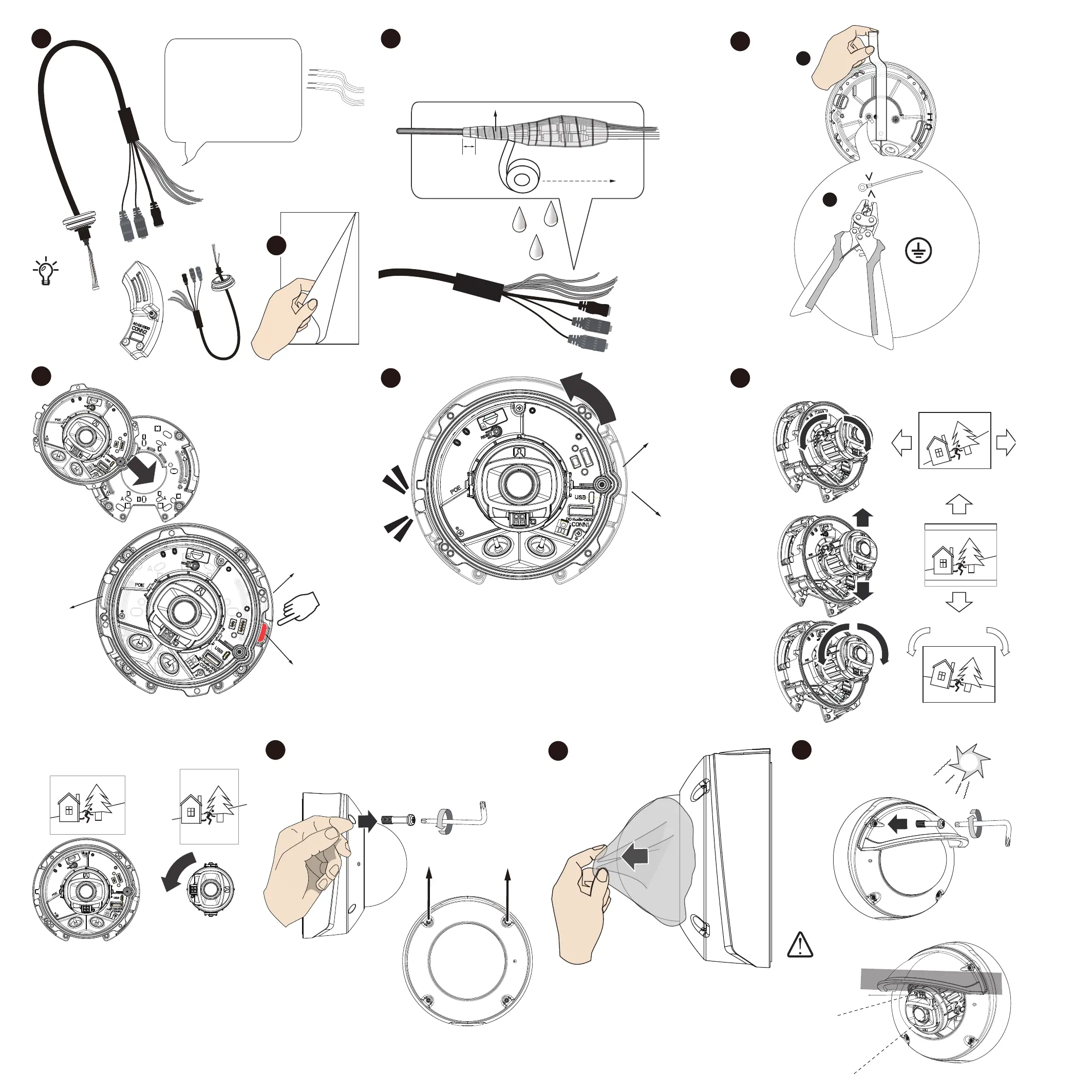
DI-: Yellow
DI1+: Blue
DO1-: Orange
DO+(12V): Brown
A
Protruding
tab
Protruding
tab
Groove
Groove
opening
1
2
3
Cable molding
Layer - Self-fusing tape
or electric tape
2cm
1. Stretch the waterproof tape by twice its length and
wind around the cables.
2. The tape should overlap the cable joints by 20mm.
3. All connectors, whether they are used or not,
should be waterproof.
12 13
14
15
16 17
18 AWG min.
3.5mm screw mm.
Green & Yellow wires
Crimping plier
Remove seal
* Use knurled washers
Protruding
tab
Groove
Extension I/O kit
x2
The top 2 screws
Top
Bottom
18
19
20
If tilted 40 ~ 60 degrees, and IR is on top,
IR
will have a black-out
area.
Steps 18 ~ 20: FD9367-EHTV-v2 Only
 Loading...