EasyManuals Logo

Vivotek FD9381-HTV User Manual

Vivotek FD9381-HTV
321 pages
To Next Page IconTo Next Page
To Previous Page IconTo Previous Page
Page #7 background imageLoading...
Page #7 background image
VIVOTEK
User's Manual - 7
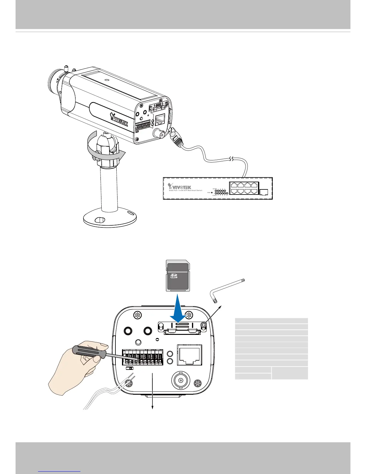
4. Install the camera stand to camera.
5. Connect an Ethernet cable to the camera.
TM
T6
DO+ (+5V)
DO-
DI1+
DI2+
DI3+
DI- (common ground)
RS485-
RS485+
AC/DC pw
12V or 24V, no
polarity
AC/DC pw
The DO pin can provide a 5V output, and the max. load is 50mA.
6. Install an SD card, and, if preferred, connect DI/DO wires to the terminal block The AC/
DC pins can accept either 12V or 24V power input with no polarity.

Table of Contents

Other manuals for Vivotek FD9381-HTV

Questions and Answers:

Question and Answer IconNeed help?

Do you have a question about the Vivotek FD9381-HTV and is the answer not in the manual?

Vivotek FD9381-HTV Specifications

General IconGeneral
BrandVivotek
ModelFD9381-HTV
CategorySecurity Camera
LanguageEnglish

Related product manuals