VIVOTEK
12 - User's Manual
icro
icro
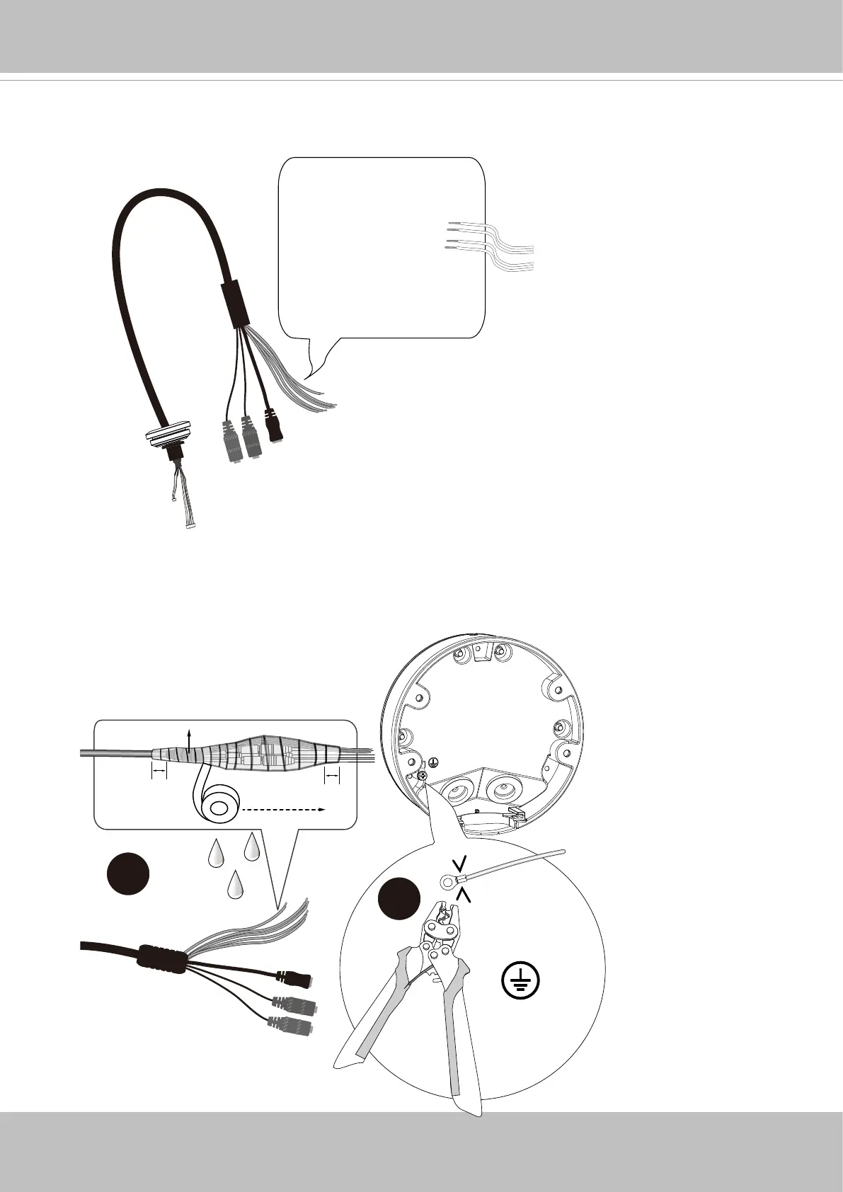
DI-: Yellow
DI1+: Blue
DO1-: Orange
DO+(12V): Brown
icro
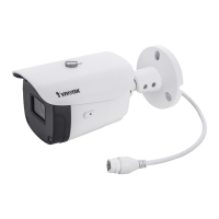
9. Below are the pinouts of the I/O combo cable. If you prefer more audio, DC, and I/
O connections, you can purchase and install an extension kit. Refer to the installation
option B section for more information.
Crimping plier
Cable molding
Layer - Self-fusing tape
or electric tape
2cm
2cm
1. Stretch the waterproof tape by twice its length and
wind around the cables.
2. The tape should overlap the cable joints by 20mm.
3. All connectors, whether they are used or not,
should be waterproof.
18 AWG min.
3.5mm screw mm.
Green & Yellow wires
* Use knurled washers
10. All cabling joints on the outside of the camera must be properly sealed for
waterproong.
Use a crimping plier to connect a grounding wire to the ground screw following the
instructions below.