Do you have a question about the VMB TL-A450 and is the answer not in the manual?
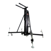
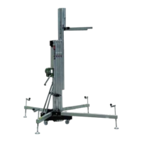
Identifies the specific model of the towerlift.
Designed for lifting audio systems like PA or Line Array.
Specifies the maximum load the towerlift can handle.
Defines the minimum load needed for safe operation.
Details the Automatic Lock System for enhanced safety.
States the maximum vertical height the lift can reach.
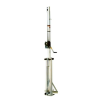
Specifies the height of the lift when it is folded.
Defines the required dimensions for the operating surface.
Provides the total weight of the towerlift unit.
Describes the long reinforced forks for load bearing.
Details the materials used in the towerlift's construction.
Outlines winch capacity and certifications.
Provides details on the steel lifting cable's properties.
Highlights adjustable feet with non-slip rubber supports.
Describes safety mechanisms for securing the legs.
Details the antirust protection and paint finish.
Mentions the spirit level for ensuring vertical alignment.
Describes swivel wheels for moving the folded lift.
Machine designed for vertical load elevation; not for people.
Instructions for placing lift on surfaces and leveling.
Warning against exceeding maximum load limits.
Emphasizes checking loads and ensuring vertical elevation.
Ensuring legs are correctly placed and secured with pins.
Lift must not be used on vehicles or other mobile surfaces.
Securing lift firmly on the ground in windy conditions.
Lift must not be moved while carrying a load.
Prohibits personnel from being below the load or in the operating zone.
Caution regarding obstacles above and below the extended lift.
Do not use stepladders on the lift or as a support.
Regularly check cable for damage; use only VMB steel cables.
All sections must be lowered and legs secured for transport.
Do not grease winch brake; it has a special resistant solution.
A minimum load of 25Kg is required for the brake to function.
Never detach the winch crank when lift is loaded or extended.
Only original replacement parts should be used.
Placing the lift on a firm surface and preparing it for use.
Steps for deploying legs and reinforcement struts.
Checking and adjusting the lift's vertical alignment.
Releasing and positioning forks for load bearing.
Instructions on how to place loads, respecting distance and center of gravity.
Warning about forces and potential damage when using multiple towers.
Table showing maximum load capacity based on distance from the tower.
Explanation of the Automatic Lock System and Inertial Lock Security.
Steps for lifting the carriage and profiles using the winch.
Procedure to hold the tower at an intermediate position.
Detailed steps for safely lowering the lift sections.
Steps for folding the machine and preparing it for transport.
Regularly check cable for damage and replace if necessary.
Periodic greasing of gearing, bearings, and sections is recommended.
Recommendation for annual inspection by an authorized dealer.
Emphasizes using only original spare parts to maintain warranty and safety.
The lift is covered by a 2-year warranty from the date of purchase.
Details warranty for defects and exclusions like improper use or modification.
Diagrams and part numbers for profiles and bars.
Diagrams and part numbers for base components.
Diagrams and part numbers for the winch assembly.
Diagrams and part numbers for the lifting carriage.
Diagrams and part numbers for the legs and related parts.
| Brand | VMB |
|---|---|
| Model | TL-A450 |
| Category | Lifting Systems |
| Language | English |