Page 9 of 16
STEP 8: SEAT ASSEMBLY
Attach the two seat sliders to the seat base using four (4) M8*35mm Socket Cap Machine Screws (No. 6), and four (4)
M8 Flange Nuts (No. 8) as shown in FIGURE 8A. Remember to place four (4) M8 silver-colored washers (No. 20) between
the bottom of sliders and top of the seat support brackets. This will ensure that the left and the right-side mounts have
adequate clearance for forward and aft movement. HINT: You can move the sliders to forward/aft position to provide
access to slider mounting holes. Note the adjustment slider handle location and lift the handle UP to allow movement.
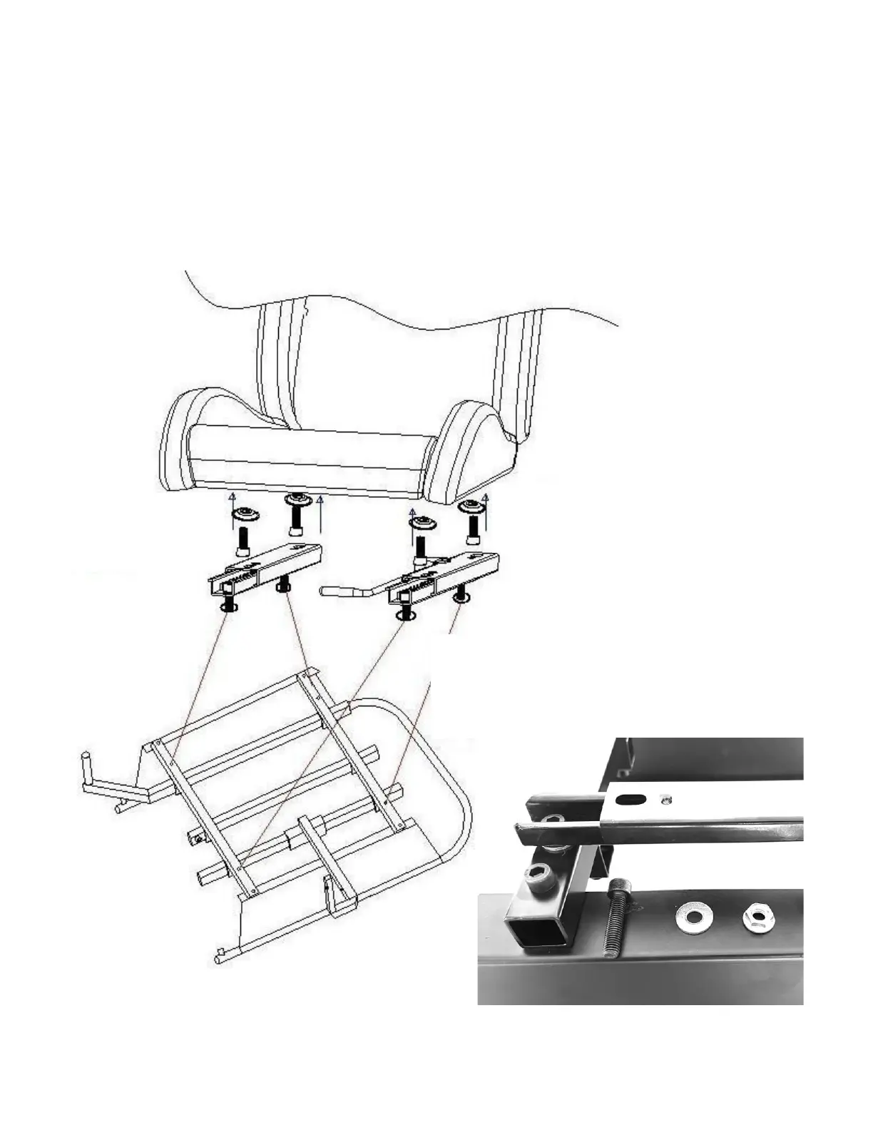
Next, attach the seat to the two sliders as shown in FIGURE 8B taking care that you place the four (4) dish-shaped Seat
Spacers (No. 18) between the sliders and the seat as shown in FIGURE 8C.
FIGURE 8A: ATTACHING THE SEAT SLIDERS TO SEAT BASE
FOUR (4) M8*35MM SOCKET CAP MACHINE SCREWS (NO. 6)
FOUR (4) M8 WASHERS (NO. 20)
FOUR (4) M8 FLANGE NUTS (NO. 8)
 Loading...