Page 8 of 16
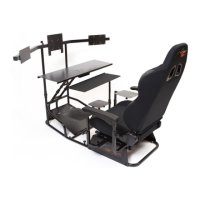
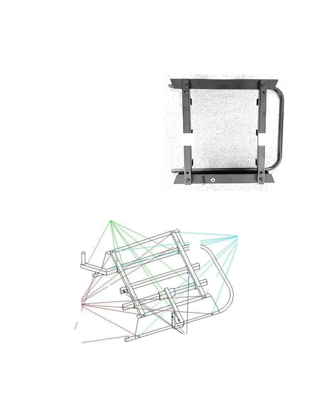
STEP 7: SEAT SUPPORT ASSEMBLY
Continue the assembly of the seat base as shown in FIGURE 7 with the two cross braces (#1) and the left (#2), center
(#3) and right (#4) square tubes. Note that the seat support brackets attach to the OUTERMOST holes on the two cross
braces and that the open square profiles on the cross braces point towards the floor. You may need to apply some
pressure and bend the seat risers outward as you insert the four (4) M8*35mm Socket Cap Machine Screws through the
cross braces. Partially thread the Machine Screws with Knobs into the open square channels under cross braces which
will later be used to secure the left, center, and right mounts.
FIGURE 7: SEAT SUPPORT ASSEMBLY
 Loading...