Page 7 of 16
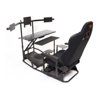
STEP 5: ATTACHING AVIONICS | WORK TABLE TO MONITOR BASE
Attach the assembled table and support structure to the monitor base and tighten the plastic adjustment plastic nuts
(circled) lightly as shown in FIGURE 5. You will be able to adjust the distance and angle of the table to suit your
preferences after the entire assembly process is complete.
FIGURE 5: ATTACHING THE AVIONICS TABLE TO MONITOR BASE
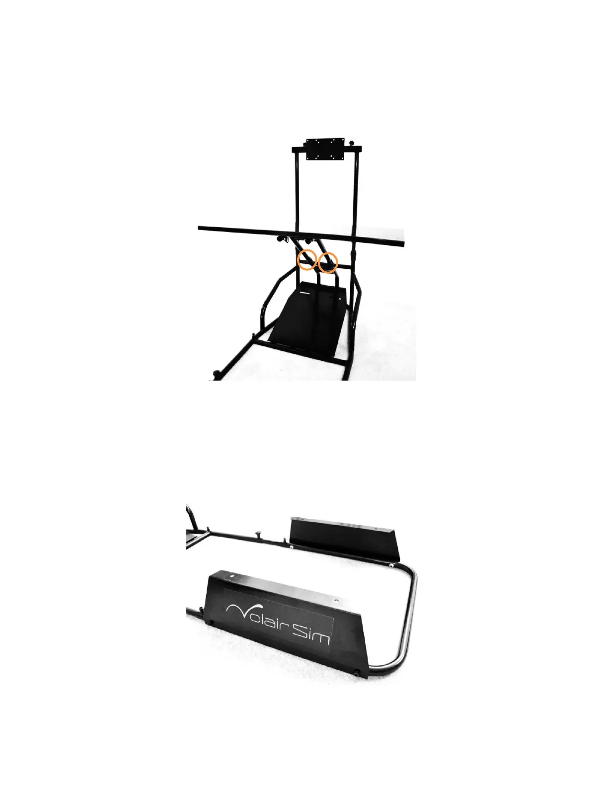
STEP 6: SEAT RISER ASSEMBLY
Attach seat risers to the seat base using four (4) M8*35mm Socket Cap Machine Screws (No. 6) and four (4) M8 Flange
Nuts (No. 8) as shown in FIGURE 6 below.
FIGURE 6: ATTACHING SEAT RISERS TO SEAT BASE