QUICK START TUTORIAL VOLTECH AT3600 USER MANUAL
PAGE 2.3.2 VPN 98 - 024 GETTING STARTED
Having started the editor program by double-clicking with the left mouse button on
the editor icon, the first thing to do is to ‘draw’ a schematic of the transformer to be
tested.
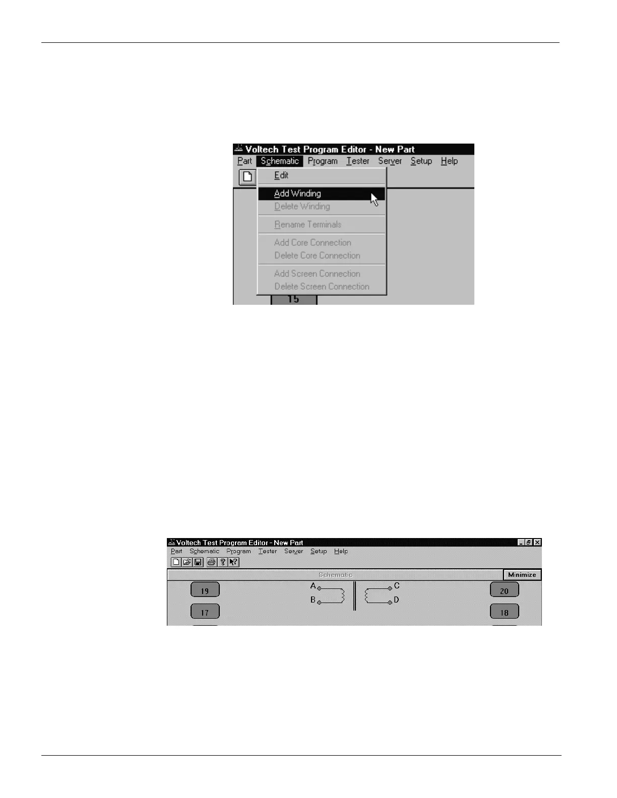
Using the left mouse button, click on ‘Schematic’ on the Top Level menu bar, and
select ‘Add Winding’ from the menu.
You will now see a winding with two terminals, floating below the mouse
pointer.
Place the winding on the left hand side of the screen and press the left mouse button.
A dialogue box will ask you to name the terminals of the winding; the cursor will be
in the box for Terminal 1.
Type the name of the Terminal 1 (e.g. ‘A’).
Press TAB to move to the Terminal 2 box, and type the name of the second
terminal (e.g. ‘B’) in that box. Then click OK or press [Enter].
Repeat steps 1-3 to create a second winding.
This time place the winding on the right hand side of the screen, a mirror image
of the first winding, and use different terminal names (e.g. ‘C’ and ‘D’). The
screen should then look like this:
 Loading...