15
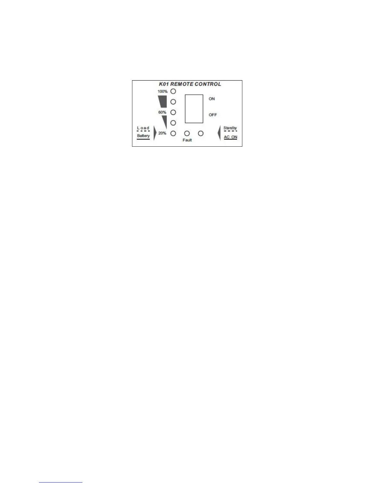
Appendix I: Remote Control
Remote Control Switch
●
Power ON/OFF Switch
Power ON/OFF switch is to turn the inverter on or off.
●
Battery Capacity/Load Voltage indicator
Load: Slow flash, 1time per second. Show the approximate connected equipment load level. Five
Levels---20%,40%,60%,80%,100%.
Battery: Solid green. Show the battery residual capacity.
Five Levels---20%,40%,60%,80%,100%.
Transfer time(Between Load and battery ): Every 8seconds
●
Standby/AC ON Indicator
Standby: Slow flash, load power is less than 5% of rated power or standby.
AC ON: Solid green. Inverter’s output is continuous.
●
Fault: Turns red to show fault, refer to Troubleshooting of Inverter Manual.
Connecting the Communications Cable
The communications cable is 3meters, 6-conductor cable (wired like a normal telephone-type
cable). This cable is connected to the RJ11 jack on the rear of the remote control and to the
REMOTE port located on the rear of the inverter.
Notice:
The Inverter’s ON/OFF Switch and Remote control’s ON/OFF Switch are in parallel.
To use the remote control to turn the Inverter OFF, You must have the inverter’s ON/OFF
Switch set to OFF. And vice- versa.
 Loading...