Fig. 1
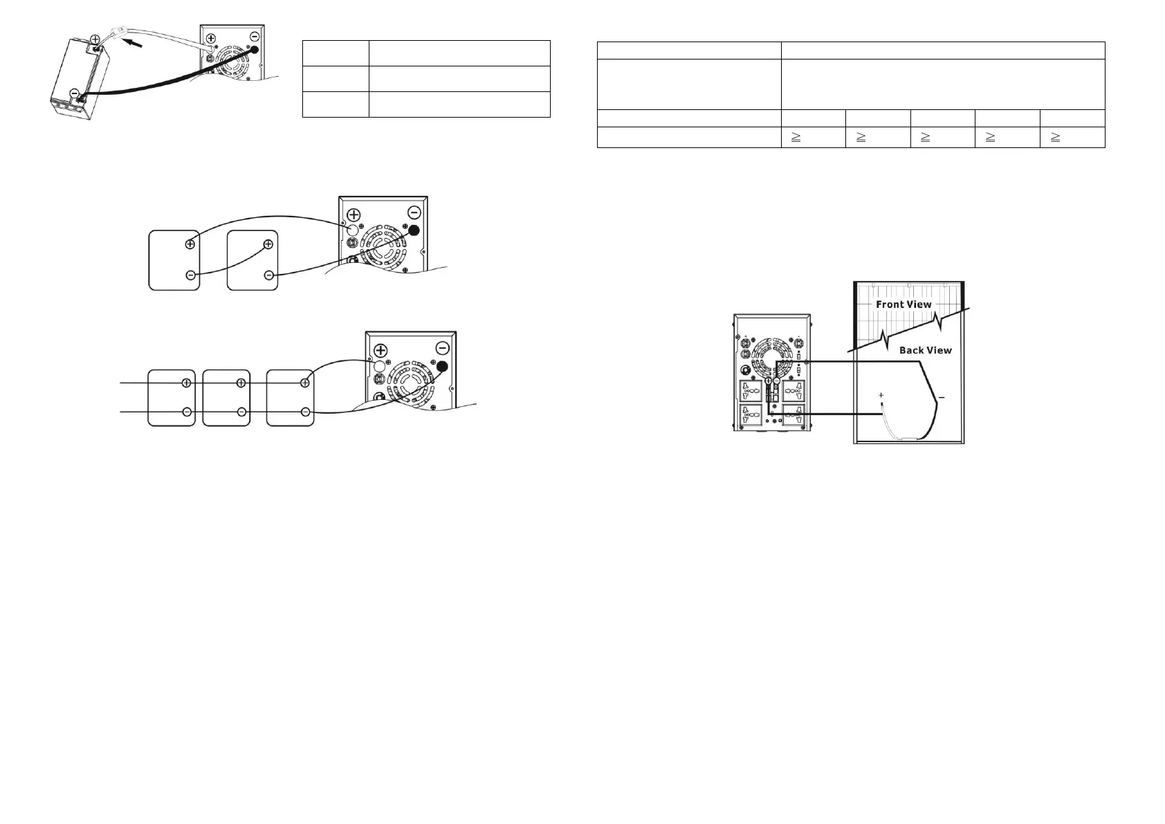
2) Multiple batteries in series connection (Refer to Fig. 2): All batteries must be equal
in voltage and amp hour capacity. The sum of their voltages must be equal to the nominal
DC Voltage of the unit.
Fig 2
3) Multiple batteries in parallel connection (Refer to Fig. 3): Each battery's voltage
must be equal to the Nominal DC Voltage of the unit.
Fig 3
Step 3- Make sure to connect the polarity of battery side and the unit correctly.
Positive pole (Red) of battery to the positive terminal (+)of the unit.
Negative pole (Black) of battery to the negative terminal (-) of the unit.
Step 4- Put the covers back to the external battery terminals.
Step 5- Take the DC breaker on.
Connect to Utility and Charge
Plug in the AC input cord to the wall outlet. The unit will automatically charge the connected
external battery even though the unit is off.
Connect to Device
Simply plug devices to battery supplied sockets. During power failure, it will provide continuous
power to connected devices.
Connect to Solar Panel (only for the model is equipped with solar charger)
To prevent any damage to the solar charger, please DO select the solar panel and battery
capacity according to recommended specifications below.
Maximum Output Voltage
(Vm)
40 VDC for 1K, 60 VDC for 2K
*1K: Maximum open-circuit voltage (Voc) < 40V
2K: Maximum open-circuit voltage (Voc) < 60V
Maximum output current (Im)
Suggested battery capacity
Step 1- Connect one cable to the positive(+) pole of solar panel and solar charger positive
(+) terminal.
Step 2- Connect the other cable to the negative (-) pole of solar panel and solar charger
negative (-) terminal.
Step 3- Check the solar charging indicator. If the green LED flashes, it means that batteries
are charged by solar power. When the batteries are fully charged, the green LED will be
lighting. If there is no solar power available, the green LED will be off. If any fault occurs on
charger, the red LED will light up. (See following chart)
6. Operation
Power On/Off
Once the inverter has been properly installed, press the power switch to turn on the unit. The
unit will work automatically in line mode or inverter mode according to input utility power's
status. When press the power switch again, the unit will be turned off.
Operation Mode Selector
a). UPS: Setting for precious electronic devices
If you select this mode, the transfer time will become 10ms for precious electronic devices
during battery mode. You can connect the computer systems or other precision home
equipment when you select this operation mode.
b). Inverter: setting for home appliances
If you select this mode, the transfer time will become 20ms during battery mode. You can
connect the home equipments, such as light bulb, fluorescent tube, fan, or TV on this
mode.
Charging Current Selector
a) 20A: setting battery charging current at 20A
b) 10A: setting battery charging current at 10A
Nominal Battery DC Voltage
 Loading...