Do you have a question about the Volvo Penta TAD1240GE and is the answer not in the manual?
Provides essential safety guidelines for operating and maintaining the engine, covering daily checks, fuel handling, and operational hazards.
Details safe procedures for lifting the engine, emphasizing the use of designated lifting eyes and proper equipment for balance.
Highlights the risks associated with batteries, including explosion hazards from oxyhydrogen gas and improper connections.
Warns against using starting spray with pre-heating systems due to explosion risk in the intake tract.
Advises caution around hot engine components and fluids to prevent burns during operation or maintenance.
Covers fire and explosion risks related to fuel, lubricating oil, and flammable materials, emphasizing safe handling and storage.
Details flammability risks of fuels and oils, safe fueling practices, and proper storage of oil-soaked rags.
Warns that using non-original parts may increase the risk of explosion or fire due to design differences.
Provides guidance on handling hazardous chemicals safely, including ventilation and protective measures.
Offers safety precautions for the lubrication system, such as avoiding hot oil contact and ensuring proper system pressure.
Details safety measures for the cooling system, particularly regarding hot coolant and pressure release.
Advises on fuel system safety, including hand protection against pressurized liquids and preventing fuel spills.
Outlines safety procedures for the electrical system, including disconnecting power before servicing.
Highlights Volvo Penta's commitment to environmental responsibility and the user's role in preserving it through proper operation.
Explains the recommended procedure for the initial 10 hours of engine operation to ensure proper break-in.
Stresses the importance of using recommended fuel and oil grades and adhering to change intervals.
Emphasizes the benefits of regular maintenance and using Volvo Penta original parts for engine longevity.
Details special requirements for emissions-certified engines, including maintenance and service protocols.
Outlines the limited warranty coverage for the industrial engine and the owner's responsibilities.
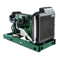
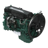
Provides a detailed overview of the engine's mechanical and system components, including engine block, fuel, lubrication, and cooling systems.
Explains how to locate and interpret engine identification plates and numbers for service and reference.
Illustrates and identifies key components and their locations on the engine for easy reference.
Describes the Electronic Diesel Control (EDC III) system, its functions, and its role in engine management.
Details the Control Interface Unit (CIU) and Display Unit (DU) used with the EDC III system for monitoring and control.
Explains the functions and operation of the DCU control panel, including engine control, monitoring, and diagnostics.
Guides users through navigating the DCU system menus for accessing engine data, settings, and diagnostics.
Describes the manual activation of engine pre-heating via the EMS system for cold starts.
Explains how to activate or deactivate droop mode and set governor parameters for engine speed control.
Details how to access and interpret fault codes and diagnostic information displayed by the system.
Instructs on how to reset trip data, such as fuel consumption, within the system's menus.
Covers parameter settings for the engine's control systems, including application, units, language, and customer parameters.
Details specific parameter settings for Genset applications, including engine speed and alarm limits.
Explains how to configure throttle control modes, idle voltage, and maximum voltage settings.
Guides on adjusting display contrast, backlight time, and brightness for optimal readability.
Provides details on engine and DCU hardware, software, and dataset identification numbers.
Outlines essential pre-start checks, including oil level, fuel cocks, coolant levels, and instrument verification.
Details the procedure for starting the engine using the EMS 2 system, including pre-heating and starter motor limits.
Explains the operation of the Volvo Penta start lock system, including key positions and pre-heating activation.
Describes an alternative method for pre-heating the engine, which may activate automatically based on temperature.
Provides procedures and recommendations for starting the engine in extremely cold conditions, including fuel and oil selection.
A critical warning against using starting spray due to the severe risk of explosion in the intake tract.
Details the correct and safe procedure for starting the engine using booster batteries, emphasizing connection order.
Advises on regularly checking engine instruments during operation for normal readings and potential issues.
Explains how the EMS 2 system indicates faults via alarms, lamps, and audible warnings, referring to diagnostic functions.
Warns against prolonged low-load operation, detailing potential issues like oil consumption and carbon buildup.
Recommends running the engine without load for a few minutes before shutdown to stabilize temperatures.
Provides the standard procedure for stopping the engine, involving disengaging the clutch and using the STOP button.
Details post-shutdown checks, including inspecting for leaks and switching off the main switch for extended periods.
Describes the location and function of the auxiliary stop control for emergency engine shutdown.
Introduces the importance of preventative maintenance and using genuine Volvo Penta parts for engine reliability.
Lists essential checks to be performed daily before the first engine start-up, such as fluid levels and inspections.
Specifies maintenance tasks required every 50 operational hours or 12 months, such as fuel filter draining.
Outlines the initial maintenance tasks to be performed after the first 150 operational hours, including oil change.
Defines intervals for oil and oil filter changes based on operational hours or 12 months.
Specifies periodic maintenance tasks, including fuel tank draining and drive belt checks, every 400 hours or 12 months.
Lists maintenance actions required every 800 operational hours or 12 months, including charge air pipe checks and filter changes.
Details maintenance tasks, such as coolant filter change, required every 1000 operational hours or 6 months.
Specifies less frequent maintenance tasks, like turbocharger and valve play checks, at 2000 operational hours.
Outlines annual maintenance checks, including EDC system diagnostics and air filter replacement.
Defines long-interval maintenance for cooling system checks and coolant changes.
Specifies initial maintenance tasks for a newly rebuilt engine, such as valve play adjustment.
Covers general maintenance aspects for the engine, including safety warnings and initial inspections.
Details the importance of regular visual inspections of the engine and compartment for early detection of issues.
Instructs on checking charge air pipes and clamps for leaks or damage, and replacing as needed.
Provides guidance on checking and adjusting drive belts, including specific tension measurements for generator belts.
Outlines the step-by-step procedure for safely replacing the generator drive belt.
Explains how to check the air filter indicator and replace the filter when necessary, with warnings about reuse.
Covers essential maintenance tasks for the lubrication system, including oil change intervals and viscosity.
Details oil change intervals based on fuel sulfur content and oil grade, with a maximum 12-month limit.
Provides guidance on selecting the correct oil viscosity based on ambient temperature for optimal lubrication.
Specifies the required volume of engine oil, including oil filter changes, for horizontal installations.
Instructs on how to correctly check and add engine oil, emphasizing not to overfill.
Details the procedure for changing the engine oil, including safety warnings and notes on warm oil.
Provides instructions for safely changing the engine oil filters, including tightening specifications.
Covers maintenance of the cooling system, including coolant mixture ratios and water quality requirements.
Explains the correct mixture of Volvo Penta Coolant and water for optimal engine protection and freezing point.
Specifies the required water quality parameters for mixing with coolant to ensure engine protection.
Details how to check the coolant level, emphasizing safety precautions when the engine is warm.
Provides instructions for adding coolant to the system, including proper filling techniques and air bleeding.
Outlines the procedure for safely draining the cooling system, including locating drain cocks and removing plugs.
Describes the process of flushing the cooling system to clean it, including the use of flushing agents.
Details the procedure for changing the coolant filter, including valve operation and filter tightening.
Covers maintenance of the fuel system, including fuel specifications and safe fueling practices.
Lists the national and international standards that market fuel must meet, including sulfur content requirements.
Provides instructions for safely changing the fuel filter, emphasizing cold engine operation and purging.
Details the procedure for changing the fuel pre-filter and transferring the water monitor.
Explains how to drain condensation water and fuel from the fuel pre-filter safely.
Describes the process of bleeding the fuel system to remove air after filter changes or other interventions.
Covers maintenance and safety aspects of the electrical system, including the main switch and fuses.
Explains the correct operation of the main switch to prevent damage to the generator and electronics.
Details the location and function of the engine's electrical system fuse, and actions for frequent fuse blowing.
Covers routine maintenance for batteries, including cleaning, electrolyte level checks, and pole protection.
Provides safety guidelines and procedures for charging batteries, emphasizing ventilation and avoiding sparks.
Illustrates the electrical components and their connections on the engine for reference.
A table listing common engine symptoms and their potential causes, guiding users to specific troubleshooting steps.
Explains how the diagnostic system detects and reports malfunctions using fault codes on the instruments.
Describes how active faults are indicated on the DCU/DU and Easy Link instruments, including warning messages.
Explains how inactive (rectified) faults are indicated on different instrument types.
Details how engine operation is affected by different fault severities, ranging from no impact to engine shutdown.
Guides on how to read fault codes depending on the equipment used (DCU, DU, CIU) and where to find remedies.
Instructs on reading fault cause messages displayed on the DU, including warning and alarm notifications.
Details the process of reading fault cause information from the DCU, including accessing the error list.
Explains how to read fault codes indicated by flashing diagnostic lamps on the instrument panel for CIU systems.
Describes how fault codes are displayed on the tachometer display of Easy Link instruments when used with a CIU.
Indicates that there are no active faults detected in the engine management system.
Identifies a fault caused by water in the fuel, requiring the primary fuel filter to be emptied.
Indicates a low coolant level, triggering a warning and potential engine power reduction.
Reports a fault related to the coolant level sensor, potentially due to short circuit or sensor failure.
Indicates a fault with the flywheel speed sensor, affecting engine starting and running.
Reports a fault with the camshaft drive speed sensor, leading to difficult starting but normal running.
Indicates an issue with engine speed, potentially too high or related to sensor function.
Flags a fault with the speed potentiometer connected to the CIU, affecting engine idle control.
Reports a fault with the water-in-fuel indicator, possibly due to cable issues or indicator failure.
Indicates a fault with the oil pressure sensor, typically a short circuit or open circuit.
Reports a fault with the charge air temperature sensor, often due to wiring or sensor issues.
Flags a fault with the coolant temperature sensor, potentially activating pre-heating when the engine is hot.
Indicates a fault with the charge pressure sensor, potentially causing increased engine smoke under load.
Reports an issue with charge pressure, which may lead to reduced engine power.
Flags a fault with the fuel pressure sensor, typically due to wiring or connection problems.
Indicates a fault with the oil temperature sensor, often related to wiring or connection issues.
Reports a fault related to fuel pressure, potentially low supply pressure affecting engine operation.
Flags a fault with the battery voltage in the EDC system, possibly due to alternator or battery issues.
Indicates a fault with the oil pressure alarm lamp, possibly a short circuit or open circuit.
Reports a fault with the coolant temperature alarm lamp, potentially affecting its function.
Flags a fault with the operation indication lamp, possibly due to wiring or connection issues.
Indicates a fault with the overspeed alarm lamp, potentially affecting its ability to signal overspeed conditions.
Reports an electrical fault related to the coolant temperature alarm lamp circuit.
Flags a fault with the start output or start motor relay, preventing engine starting or causing immediate startup.
Indicates a fault with the stop input for the EDC, potentially allowing only auxiliary stop.
Reports a fault with the starter input for the CIU, preventing engine start or causing immediate startup.
Flags a fault with the stop input for the CIU, potentially causing engine shutdown or inability to stop.
Indicates a fault with the preheating relay, preventing activation or causing constant connection.
Reports a fault with the air filter sensor, affecting engine performance monitoring.
Flags a low oil level fault, triggering a warning indication and potentially reducing engine output.
Indicates a fault with high oil temperature, triggering a warning and limiting engine output.
Reports a fault with the oil level sensor, possibly due to wiring or sensor failure.
Flags a fault for high coolant temperature, leading to reduced engine power.
Indicates a fault for high charge air temperature, resulting in reduced engine power.
Reports a fault with the data link (CAN) to the CIU, affecting instrument and warning lamp operation.
Flags an internal fault in the control module related to the data link (CAN) for EDC.
Indicates low oil pressure, leading to reduced engine power.
Reports a fault with battery voltage in the CIU, affecting engine starting.
Flags a fault with injector cylinder #1, potentially causing 5-cylinder operation and reduced performance.
Indicates a fault with injector cylinder #2, potentially causing 5-cylinder operation and reduced performance.
Reports a fault with injector cylinder #3, potentially causing 5-cylinder operation and reduced performance.
Flags a fault with injector cylinder #4, potentially causing 5-cylinder operation and reduced performance.
Indicates a fault with injector cylinder #5, potentially causing 5-cylinder operation and reduced performance.
Reports a fault with injector cylinder #6, potentially causing 5-cylinder operation and reduced performance.
Flags a fault with the J1587 data link, impacting communication between control units.
Indicates a fault with the sensor power supply, affecting oil pressure and charge air sensor readings.
Reports a fault with the EEPROM data set memory in the CIU, potentially causing factory setting reset.
Flags a fault within the CIU control module, potentially leading to engine idle or inability to start.
Indicates a memory fault in the engine management system, potentially preventing engine start.
Reports a fault with the EEPROM data set memory in the EDC, potentially preventing engine start.
Flags an internal fault in the EDC control module, potentially causing engine misfires or failure to start.
Provides general technical specifications for different engine models, including displacement, bore, stroke, and weight.
Details technical data for the lubrication system, including oil pressure, oil filter type, and pump type.
Specifies the number and tightening torque for full-flow and bypass oil filters.
Indicates the type of oil pump used in the engine (Gear driven).
Provides technical data for the fuel system, including injection order, feed pump pressure, and overflow valve pressure.
Details technical specifications for the cooling system, including pressure valve opening, volume, and thermostat settings.
Presents technical data for the electrical system, including system voltage, alternator specifications, and battery capacity.
| Brand | Volvo Penta |
|---|---|
| Model | TAD1240GE |
| Category | Engine |
| Language | English |