Specifications
Electrical system, specifications 177
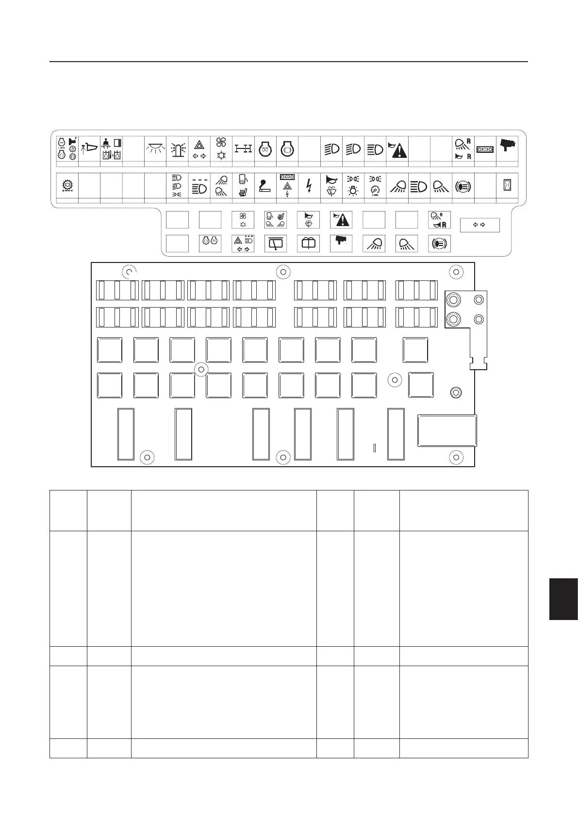
Fuses
Electrical distribution box
Mark-
ing
Rated
current
Description Mark-
ing
Rated
current
Description
1 5 A Switch exhaust brake, engine brake,
switch brake pedal, increased engine
rpm, shift lock-out, load and dump brake,
dump lever lock-out position
Position sensor throttle pedal, position
sensor gear selector, position sensor
retarder pedal, position monitor low
range/high range, position monitor
throttle pedal, position monitor retarder
pedal, position monitor parking brake
12 15 A E-ECU, Feed 28VD C E-
ECU (including function
engine stop)
2 5 A Position monitor dump body 13 5 A Low beam, right
3 5 A Position monitor seatbelt, position
monitor seat cushion, position monitor
shut-off valve hydraulic oil tank, pressure
monitor return oil filter hydraulic oil,
pressure monitor return oil filter cooling
fan oil, socket service display unit
14 5 A Low beam, left
4 15 A Switch parking brake 15 5 A High beam, right
T-ECU
D-ECU
T-E CU
V-ECU
(V2-E C U )
15A 15A 15A 15A 15A 15A 15A 15A 10A
RF3601
VOLVO CE 15020138
10A5A 5A 5A 5A
42414039
5A5A15A15A
38
15A
37
10A
36
5A
35
5A
34
5A
32
5A
31
5A
33
15A
30
10A
27
15A
25
15A
26
15A
29
15A
28
5A
24
5A
23
5A
22
123
G
4 5 6 7 8 9 10 11 12 13 14 15 16 17 18 19 20 21
5A
5A 10A 10A
RE4 RE5 RE6 RE7 RE8 RE9RE3RE2RE1
RE10
T-ECU
V-E C U
(V2-E C U )
T- E C U V -E C U
D-ECU
(V2-ECU)
RE11
E-ECU
E-ECU
RE12 RE13 RE14 RE15 RE16 RE17 RE18
25A5A15A 3A
V-ECU
(V2-E C U )
D-ECU 31A
STOP
Tachograph
CareTrack
Tachograph
CareTrack
1048483
V1052901
123456789101112
12345678
10
P1 P2 P3 P4 P5
P7
P6
11 12 13 14 15 16 17 18
RFX
9
2322 24 25 26 27 28 29 30 31 32 33
13 14 15
34 35 36
16 17 18
37 38 39
19 20 21
+30
40 41 42